
Optical disk reproducing device

a technology of optical disk and reproducing device, which is applied in the direction of optical beam source, head disposition/mounting, instruments, etc., to achieve the effect of suppressing non-linear crosstalk, high capacity, and high accuracy of recording signal

Active Publication Date: 2022-05-17
PANASONIC INTELLECTUAL PROPERTY MANAGEMENT CO LTD
View PDF10 Cites 0 Cited by
  • Summary
  • Abstract
  • Description
  • Claims
  • Application Information

AI Technical Summary

Benefits of technology

[0010]The present invention solves the above-described problems, and achieves highly accurate reproduction of a recorded signal with a high effect of suppressing crosstalk even if a track pitch is narrower than a conventional track pitch. An object of the present invention is to provide an optical disk reproducing device that achieves a further increase in capacity by improving a track density.
[0012]The optical disk reproducing device in the present disclosure has a high effect of suppressing non-linear crosstalk that occurs at a narrower track pitch than a track pitch of a conventional optical disk reproducing device, and achieves highly accurate reproduction of a recorded signal, and can achieve a further increase in capacity by improving a track density.

Problems solved by technology

In particular, while the reduction in track pitch is effective for increasing the capacity, there is a problem of crosstalk that a signal recorded on an adjacent track of a scanning track is added to a detection signal, and becomes noise due to the reduction.

Method used


Image

  • Optical disk reproducing device
  • Optical disk reproducing device
  • Optical disk reproducing device

Examples


first exemplary embodiment

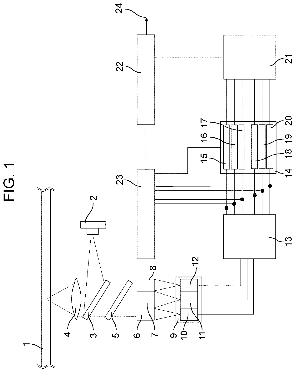
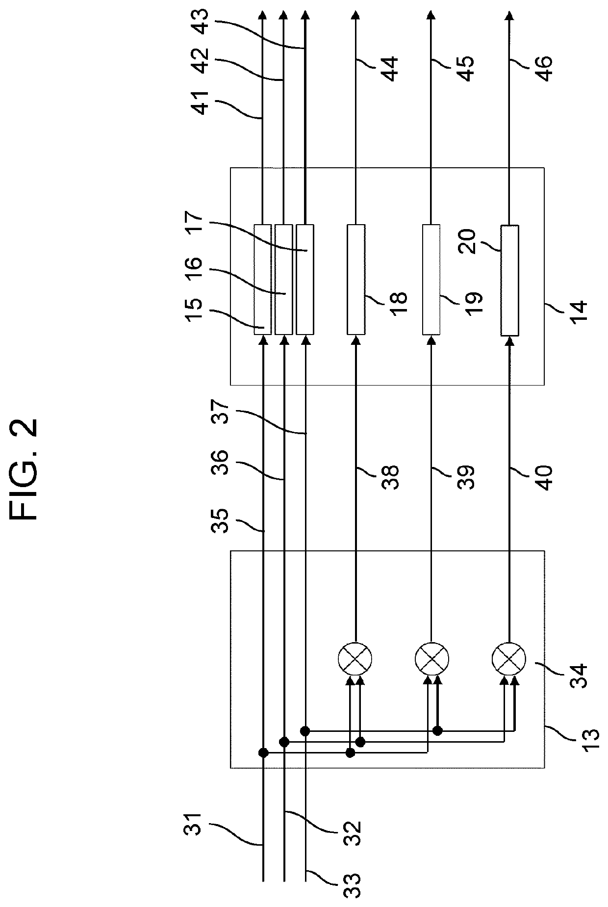
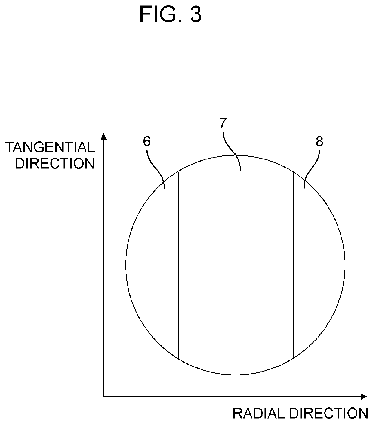
[0024]FIG. 1 is a schematic diagram showing a configuration of an optical disk reproducing device according to a first exemplary embodiment of the present invention. FIG. 2 is a diagram showing configurations of a non-linear processor and an equalization processor of the optical disk reproducing device according to the first exemplary embodiment of the present invention. FIG. 3 is a diagram showing a division configuration of a division element according to the first exemplary embodiment of the present invention.

[0025]Optical disk reproducing device 100 is a device that is recorded on optical disk 1 and reproduces data. Optical disk reproducing device 100 includes blue semiconductor laser unit 2, laser mirror 3, objective lens 4, beam splitter 5, division element 70, photodetector 9, non-linear processor 13, equalization processor 14, adder 21, reproduction signal processor 22, and gain controller 23.

[0026]Optical disk 1 has a groove-shaped track, and data is recorded on a land port...

second exemplary embodiment

[0040]FIG. 4 is a schematic diagram showing a configuration of an optical disk reproducing device according to a second exemplary embodiment of the present invention. FIG. 5 is a diagram showing a division configuration of a division element of the optical disk reproducing device according to the second exemplary embodiment of the present invention. FIG. 6 is a configuration diagram showing a non-linear processor and an equalization processor of the optical disk reproducing device according to the second exemplary embodiment of the present invention. In FIG. 4, same components as those in FIG. 1 will be denoted by same reference marks, and description thereof will be omitted. In FIG. 4, differences from FIG. 1 are that division element 71, photodetector 9, non-linear processor 78, equalization processor 79, adder 80, and gain controller 81 are used.

[0041]Division element 71 is a diffractive element manufactured to operate as a diffraction grating by forming fine grooves on a glass s...

third exemplary embodiment

[0045]FIG. 7 is a diagram showing a division configuration of a division element of an optical disk reproducing device according to a third exemplary embodiment of the present invention. In the optical disk reproducing device according to the third exemplary embodiment of the present invention, for division element 70 in FIG. 1, a configuration in FIG. 7 is replaced with the configuration of FIG. 3, and for photodetector in FIG. 1, the configuration of three photodetectors 9 are replaced with four photodetectors 9. Since change in a number of signal lines and the like with these changes in the configuration is equivalent to the change from three in the first exemplary embodiment to six in the second exemplary embodiment, the illustration will be omitted here, and a division element, which is a clear difference, will be particularly described. FIG. 7 shows central region 7 obtained by further dividing central region 7 in FIG. 3 into three in a direction corresponding to a tangential ...


PUM

PropertyMeasurementUnit
distanceaaaaaaaaaa
wavelengthaaaaaaaaaa

Abstract

An optical disk reproducing device includes a division element that divides a reflected light reflected and diffracted by an optical disk into a light flux in a central region and light fluxes in end regions; a photodetector that has a central light receiver that receives the light flux in the central region and at least two end light receivers that receive the light fluxes in the end regions, and outputs a light amount signal corresponding to a light amount of each of the received light fluxes; a non-linear processor that receives each of the light amount signals from the central light receiver and the end light receivers, and outputs linear signals and non-linear signals obtained by processing the light amount signals by linear and non-linear arithmetic operations; an equalization processor that receives the linear signals and the non-linear signals and outputs signals each amplified with a predetermined gain; an adder that adds the amplified signals and outputs an equalization signal; a reproduction signal processor that processes the equalization signal and outputs a reproduction signal and an equalization error signal; and a gain controller that receives the equalization error signal and controls an amplification gain of the non-linear signals.

Description

TECHNICAL FIELD[0001]The present invention relates to an optical disk reproducing device that reproduces information recorded on an optical disk.BACKGROUND ART[0002]As conventional optical disks, a compact disc (CD), a digital versatile disc (DVD), and a Blu-ray (registered trademark) disc (BD) are widely known. Furthermore, in recent years, an archival disc (AD) have been announced, the AD having an increased capacity for the purpose of long-term storage of data, as compared with existing optical disks, and further increase in disk capacity is expected of these optical disks.[0003]Means for increasing the disk capacity include reduction in track pitch, increase in density in a scanning line direction, and increase in recording layer. In particular, while the reduction in track pitch is effective for increasing the capacity, there is a problem of crosstalk that a signal recorded on an adjacent track of a scanning track is added to a detection signal, and becomes noise due to the red...

Claims


Application Information

Patent Timeline
Patent Type & Authority Patents(United States)
IPC IPC(8): G11B7/135G11B7/1374G11B7/09G11B7/127
CPCG11B7/1374G11B7/0941G11B7/127G11B7/005G11B7/126G11B7/1353G11B7/133G11B20/10G11B7/00718
Inventor NAKASENDO, TSUYOSHIKOMMA, YOSHIAKI
Owner PANASONIC INTELLECTUAL PROPERTY MANAGEMENT CO LTD
Learn More