
Antenna device and electronic device having same

an antenna and electronic device technology, applied in the structure of radiating elements, substation equipment, transmission, etc., can solve the problems of reducing the number of antenna modules, and reducing so as to increase the reception speed of data or the like and the transmission speed of radio signals.

Active Publication Date: 2021-10-12
SAMSUNG ELECTRONICS CO LTD
View PDF42 Cites 2 Cited by
  • Summary
  • Abstract
  • Description
  • Claims
  • Application Information

AI Technical Summary

Benefits of technology

This configuration enables efficient transmission and reception of radio frequency signals across various bands, enhancing data transmission speed and stability within the limited space of miniaturized electronic devices, while maintaining a compact and portable design.

Problems solved by technology

However, the higher the frequency band is, the stronger the directivity of the radio signal becomes, which makes the radio signal more susceptible to being reflected or blocked by an obstacle and the signal arrival distance is reduced.
However, the number of antenna modules is inevitably limited due to the limitation of the mounting space of the antenna module.
In an electronic device such as a mobile communication terminal that is miniaturized for a portable purpose, it is difficult to secure a mounting space and position for ensuring the stable performance of antenna modules.
Furthermore, it is difficult to secure an antenna device capable of ensuring stable transmission and reception performance in a very high frequency band in an electronic device equipped with various antenna devices for Wi-Fi, Bluetooth, and proximity wireless communication as well as mobile communication services.

Method used


Image

  • Antenna device and electronic device having same
  • Antenna device and electronic device having same
  • Antenna device and electronic device having same

Examples


Embodiment Construction

[0042]Hereinafter, various embodiments of the present disclosure will be described with reference to the accompanying drawings. However, it should be understood that there is no intent to limit the present disclosure to the particular forms disclosed herein; rather, the present disclosure should be construed to cover various modifications, equivalents, and / or alternatives of embodiments of the present disclosure. In describing the drawings, similar reference numerals may be used to designate similar constituent elements.

[0043]As used herein, the expression “have”, “may have”, “include”, or “may include” refers to the existence of a corresponding feature (e.g., numeral, function, operation, or constituent element such as component), and does not exclude one or more additional features.

[0044]In the present disclosure, the expression “A or B”, “at least one of A or / and B”, or “one or more of A or / and B” may include all possible combinations of the items listed. For example, the express...


PUM

PropertyMeasurementUnit
frequencyaaaaaaaaaa
frequencyaaaaaaaaaa
frequencyaaaaaaaaaa

Abstract

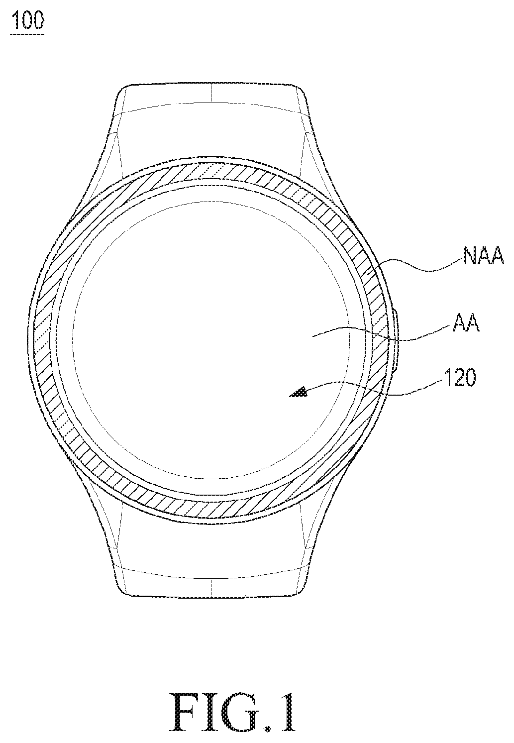
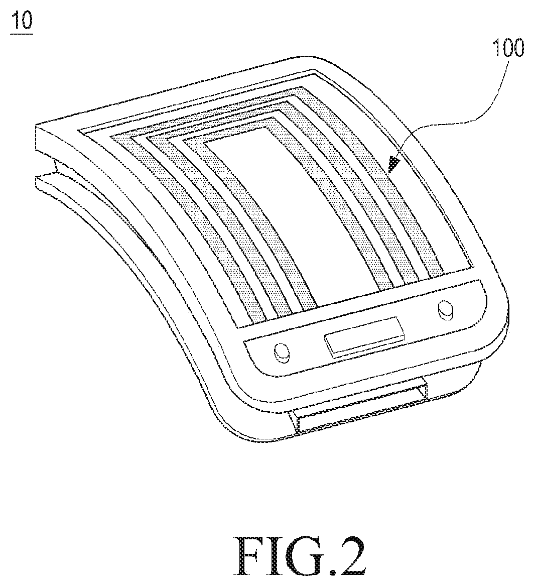
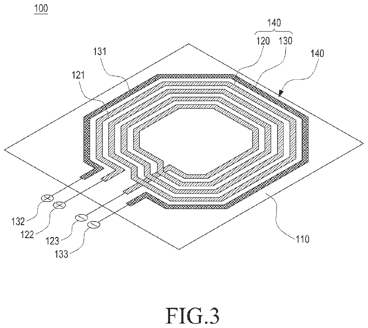
One example among various examples of the present invention provides an antenna device and an electronic device having the same, and the antenna device can comprise: a conductive film member including mesh grid areas composed of transparent conducting wires and electrodes; and a radiation pattern path unit formed between the mesh grid areas. In addition, the antenna device and the electronic device having the same, according to the present invention, can be implemented through other various examples.

Description

PRIORITY[0001]This application is a National Phase Entry of PCT International Application No. PCT / KR2016 / 012939, filed on Nov. 10, 2016, and claims priority to Korean Patent Application No. 10-2015-0157760, filed on Nov. 10, 2015, the contents of each of which are incorporated herein by reference.BACKGROUND1. Field[0002]Various embodiments disclosed herein relate to an electronic device, and more particularly, to an antenna device for implementing a wireless communication function and an electronic device having the antenna device.2. Description of Related Art[0003]Wireless communication techniques have recently been implemented in various schemes (e.g., a wireless Local Area Network Communication (w-LAN) that are represented by the Wi-Fi technique, Bluetooth, and Near Field Communication (NFC)), in addition to a commercialized mobile communication network connection. Mobile communication services have evolved from a first-generation mobile communication service, which is centered o...

Claims


Application Information

Patent Timeline
Patent Type & Authority Patents(United States)
IPC IPC(8): H01Q1/24H01Q1/27H01Q1/38H01Q5/30H04B5/00H01Q7/00H04M1/02
CPCH01Q1/241H01Q1/273H01Q1/38H01Q5/30H04B5/0025H01Q7/00H04M1/0202H04M1/026H04B5/70H04B5/43
Inventor KO, SEUNG-TAEKIM, YOON-GEONLIM, SANG-HOHONG, WON-BIN
Owner SAMSUNG ELECTRONICS CO LTD
Learn More