Flatbed embossed-printing machine and embossing plate

a flatbed embossing machine and embossing plate technology, which is applied in the field of flatbed embossing machine and embossing plate, can solve the problems of high heating time of the embossing tool by means of such resistance heaters, affecting the accuracy of embossing, and affecting the quality of embossing tools, so as to reduce the setting and reconfiguration time, shorten the heating time, and improve the productivity of the flatbed

Active Publication Date: 2021-09-14
GIETZ
View PDF30 Cites 0 Cited by
  • Summary
  • Abstract
  • Description
  • Claims
  • Application Information

AI Technical Summary

Benefits of technology

[0125]The present invention has the advantage that the reduced setting and reconfiguration times due to the shorter heating-up time lead to a higher productivity of the flat bed embossing machine. The heating-up time with the flat bed embossing machine according to the invention can thus be reduced to less than one hour.
[0126]At the same time, a more precise temperature control is possible thanks to the lower reaction times of the induction heating appliance, by which means the embossing quality can be increased and the rejection rate reduced. The range of demanding embossing tasks can be significantly widened by this.
[0127]The induction heating appliance is moreover characterised by a greatly reduced energy consumption, since the thermal energy can be produced directly in the body to be heated and an unnecessary heating of further machine parts does not take place.

Problems solved by technology

The heating of the embossing tools to the operating temperature by way of such resistance heaters however take up a lot of time.
However, the components of the press head which are now likewise involuntarily heated are also subject to thermal expansion which in turn influences the embossing accuracy.
This results in the long heating-up time which is mentioned above.

Method used


Image

  • Flatbed embossed-printing machine and embossing plate
  • Flatbed embossed-printing machine and embossing plate
  • Flatbed embossed-printing machine and embossing plate

Examples


Embodiment Construction

[0141]Certain features, for example features which are not essential to the invention are not represented in the drawings, for a better understanding of the invention. The described embodiment examples are exemplary of the subject-matter of the invention or serve for its explanation and have no limiting effect.

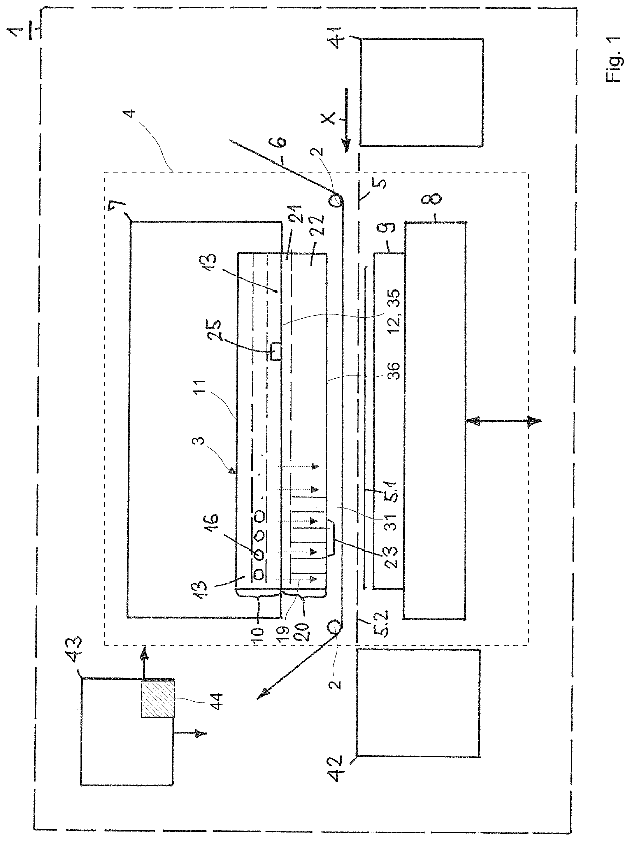
[0142]FIG. 1 shows a schematic representation of a flat bed embossing machine 1.

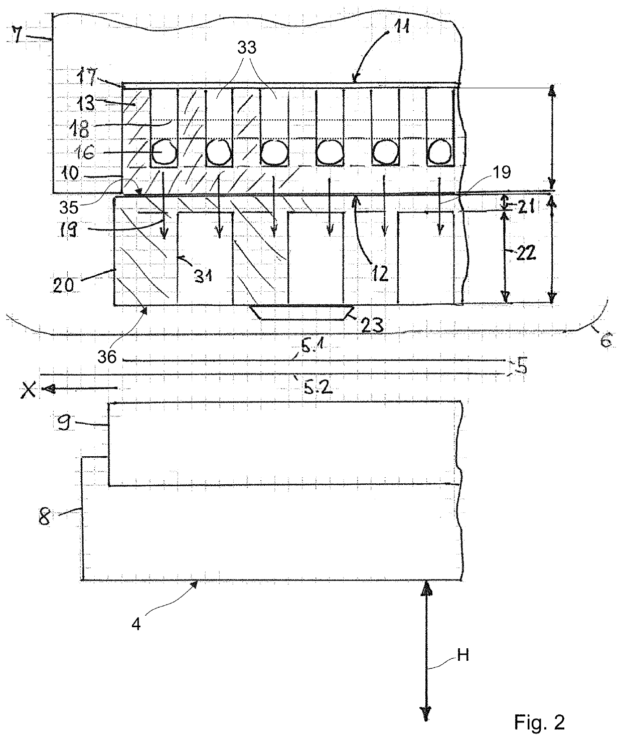
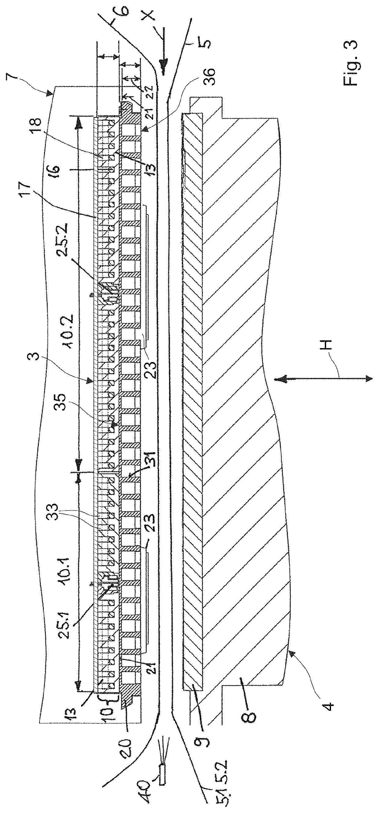
[0143]The machine (press) 1 comprises a flat bed press 4 with a printing table 8 and with a press head 7. The printing table 8 comprises a back-pressure plate 9.

[0144]A base plate 10 of an induction heating appliance 3 is arranged on the press head 7. The base plate 10 comprises a plate rear side 11 with a first support surface, and a tool plate side 12 which lies opposite the plate rear side 11 and which has a second support surface. The base plate 10 bears with the support surface of the plate rear side 11 on a fastening component of the press head 7 in an extensive (surfaced) manner and is mecha...


PUM

PropertyMeasurementUnit
operating temperatureaaaaaaaaaa
lengthaaaaaaaaaa
lengthaaaaaaaaaa

Abstract

The invention relates to a flat bed embossing machine (1) comprising a tool plate (20) with a tool side (36) for receiving at least one embossing tool and with a tool plate rear side (35) which lies opposite the tool side (36), further a base plate (10) with a tool plate side (12) which faces the tool plate rear side (35) and with a base plate rear side (11) which is lies opposite the tool plate side (12), for transmitting an embossing force which is exerted upon the tool plate (20), between the tool plate side (12) and the base plate rear side (11), as well as an induction heating appliance (3) for heating the at least one embossing tool (23). The induction heating appliance (3) comprises an inductor (16), the design of which and its arrangement between the tool plate side (12) and the base plate rear side (11) being such that a magnetic alternating field (19) which on the tool plate side (12) reaches beyond the base plate (19) and is for the inductive heating of an inductively heatable tool plate (20) can be produced beyond of the tool plate side (12) and outside the base plate (10).

Description

[0001]The invention relates to the field of flat bed embossing machine and concerns a flat bed embossing machine as well as a tool plate for a flat bed embossing machine, according to the preamble of claims 1 and 18.BACKGROUND[0002]Amongst other things, flat bed embossing machines, also called flat bed stamping machines or flat foil printing presses are used for embossed foil printing, hologram transfer, blind embossing, micro-embossing as well as structure embossing.[0003]Concerning embossed foil printing, an embossing foil is “pressed” onto a flat material with the help of an embossing tool and as a rule amid the effect of heat. The transferred foil herein lies in one plane with the flat material. A hardly noticeable to significant embossing of the flat material results, depending on the embossing tool, the pressing pressure and the flat material. Herein, the flat material is the carrier of the embossing or print embossing.[0004]Flat bed embossing machines represent a special desi...

Claims


Application Information

Patent Timeline
Patent Type & Authority Patents(United States)
IPC IPC(8): B21D37/16B44B5/02B41F19/06B21D22/02B41F33/00H05B6/14
CPCB44B5/028B21D22/02B21D37/16B41F19/064B41F33/00H05B6/14B41P2219/31
Inventor BÄNZIGER, HEINZRÖSLI, MANFRED
Owner GIETZ
Why Eureka
Try Eureka