
Single-frequency fiber amplifier with distal cladding stripper

a single-frequency fiber amplifier and distal cladding technology, which is applied in the direction of instruments, optical elements, optics, etc., can solve the problems of reducing the linewidth. , to achieve the effect of reducing the power threshold for sbs onset, reducing the maximum achievable output power of the fiber amplifier, and reducing the linewidth

Active Publication Date: 2021-08-31
MASSACHUSETTS INST OF TECH
View PDF31 Cites 1 Cited by
  • Summary
  • Abstract
  • Description
  • Claims
  • Application Information

AI Technical Summary

Benefits of technology

The patent text describes the use of a fiber amplifier with high power and narrow linewidth. The amplifier uses gain fibers with different absorptions and core sizes to achieve both high power and good beam quality. By using multiple gain fibers with smaller core sizes, the amplifier can achieve high gain without degrading beam quality. Additionally, the text explains how variations in glass chemistry can suppress stimulated Brillouin scattering (SBS) by changing the speed of sound in the gain fibers. The text also mentions the use of a cladding light stripper to remove both pump light and high-angle signal light propagating in the cladding. Overall, the patent text provides technical methods for achieving high power and narrow linewidth using fiber amplifiers.

Problems solved by technology

Unfortunately, reducing the linewidth also reduces the power threshold for SBS onset, which in turn reduces the fiber amplifier's maximum achievable output power.
Higher absorption can be accomplished by increasing the ratio of the core and cladding diameters, but a larger core diameter often results in worse beam quality.

Method used


Image

  • Single-frequency fiber amplifier with distal cladding stripper
  • Single-frequency fiber amplifier with distal cladding stripper
  • Single-frequency fiber amplifier with distal cladding stripper

Examples


Embodiment Construction

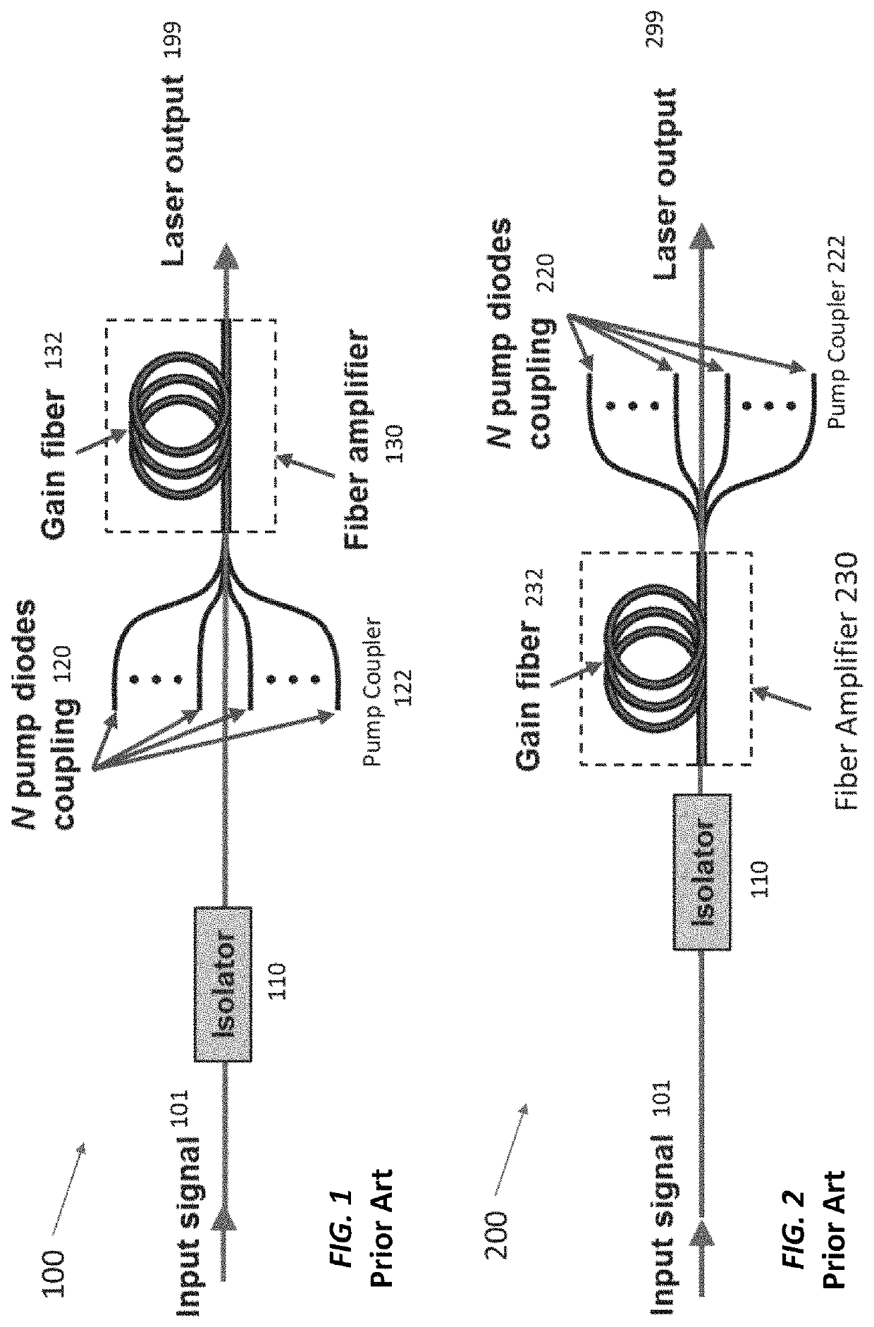
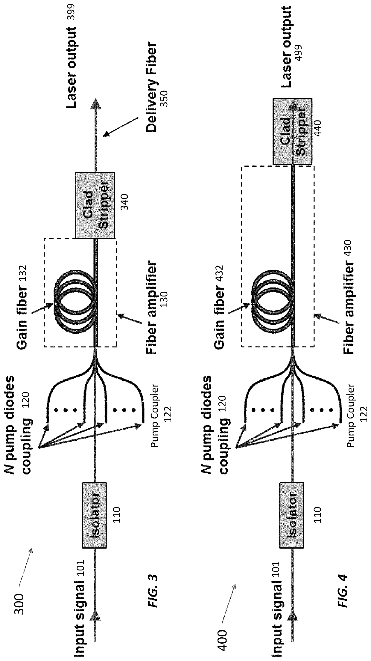
lass="d_n">[0024]The power threshold for the onset of stimulated Brillouin scattering (SBS) is proportional to the cross-sectional area of the signal beam divided by the effective fiber length, which is the fiber length weighted by the internal power (for constant power, the effective fiber length is the actual fiber length). For gain fibers, the effective length is shorter than the actual length because the sections of fiber with low optical power do not contribute significantly to SBS. In practice, for high-power fiber amplifiers, one can usually ignore the SBS contributions for sections of fiber where the power is less than half the total output power. The beam area can be enlarged by using large-mode area (LMA) fibers, but this can degrade the beam quality. The fiber length can be kept short by using high-absorption fibers and / or operating the fiber laser with low pump absorption if laser efficiency is not a driver. In other words, if the fiber is too short to effectively absorb...


PUM

PropertyMeasurementUnit
power thresholdaaaaaaaaaa
thresholdaaaaaaaaaa
thresholdaaaaaaaaaa

Abstract

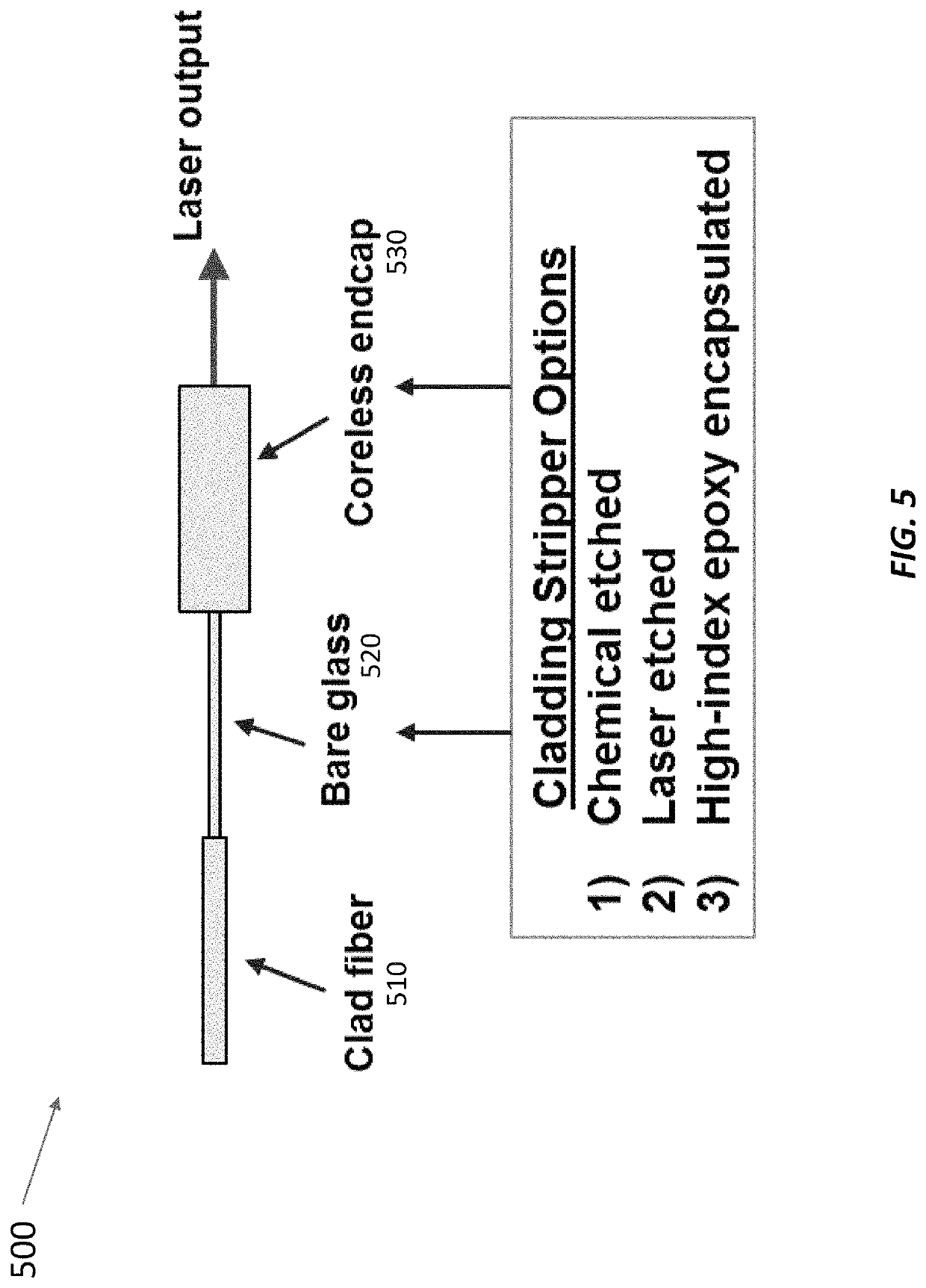
Stimulated Brillouin scattering (SBS) limits the maximum power in fiber lasers with narrow linewidths. SBS occurs when the power exceeds a threshold proportional to the beam area divided by the effective fiber length. The fiber lasers disclosed here operate with higher SBS power thresholds (and hence higher maximum powers at kilohertz-class linewidths) than other fiber lasers thanks to several techniques. These techniques include using high-absorption gain fibers, operating the laser with low pump absorption (e.g., ≤80%), reducing the length of un-pumped gain fiber at the fiber output, foregoing a delivery fiber at the output, foregoing a cladding light stripper at the output, using free-space dichroic mirrors to separate signal light from unabsorbed pump light, and using cascaded gain fibers with non-overlapping Stokes shifts. The upstream gain fiber has high absorption and a larger diameter for high gain, and subsequent gain fiber has a smaller diameter to improve beam quality.

Description

CROSS-REFERENCE TO RELATED APPLICATION(S)[0001]This application claims the priority benefit, under 35 U.S.C. § 119(e), of U.S. Application No. 62 / 869,629, filed on Jul. 2, 2019, which is incorporated herein by reference in its entirety.GOVERNMENT SUPPORT[0002]This invention was made with Government support under Grant No. FA8702-15-D-0001 awarded by the U.S. Air Force. The Government has certain rights in the invention.BACKGROUND[0003]Continuous-wave and pulsed fiber laser amplifiers are being used for an ever-increasing variety of applications in industry, for the military, and for science. They are characterized by nearly diffraction-limited beam quality and have been demonstrated to multi-kilowatt power levels. To reach power levels in the kilowatt range, the amplifiers typically use large mode area (LMA) fibers and / or are operated with 10's to 1000's GHz linewidth to mitigate the deleterious effects of stimulated Brillouin scattering (SBS).[0004]Stimulated Brillouin scattering (...

Claims


Application Information

Patent Timeline
Patent Type & Authority Patents(United States)
IPC IPC(8): H01S3/067H01S3/30H01S3/0941H01S3/094
CPCH01S3/06783H01S3/06708H01S3/06737H01S3/06758H01S3/0941H01S3/094003H01S3/302G02B6/262H01S3/06745H01S3/09408H01S3/09415H01S2301/03
Inventor AUGST, STEVEN J.YEE, KELSEYJOSE, FRANKLIN
Owner MASSACHUSETTS INST OF TECH
Learn More