Vector signal generator operating on microwave frequencies, and method for generating time-controlled vector signals on microwave frequencies

a vector signal and microwave frequency technology, applied in the direction of instruments, superconductor devices, dissimilar materials junction devices, etc., can solve the problems of unavoidable thermal noise on the transmission line that needs to be attenuated, large equipment requirements, and relatively long latency of any feedback control loop, so as to achieve the precise and lossless control of the desired phase shift, high efficiency, and low cost

Pending Publication Date: 2022-06-16
IQM FINLAND OY
View PDF0 Cites 0 Cited by
  • Summary
  • Abstract
  • Description
  • Claims
  • Application Information

AI Technical Summary

Benefits of technology

[0018]According to an embodiment each of said tunable resonators comprises a coupling element for making a coupling to said transmission line, a DC SQUID coupled between said coupling element and a reference potential, and a flux bias line of said DC SQUID for controlling a magnetic flux that penetrates a SQUID loop of said DC SQUID. This involves the advantage of precise and lossless controllability of the desired phase shift.
[0019]According to an embodiment said tunable resonators are located along said transmission line at mutual distances of a quarter wavelength of microwaves of an operating frequency of said microwave resonator. This involves the advantage of enabling the full 2π controllability with very small losses.
[0020]According to an embodiment said microwave resonator is a tunable microwave resonator that allows its resonance frequency to be tuned within a tuning range; the vector signal generator comprises a filter coupled to said output; and said tuning range of the resonance frequency of said microwave resonator allows tuning said resonance frequency selectively to a stop frequency or a pass frequency of said filter. This involves the advantage that on-off switching of the produced microwave signals is possible in a highly effective manner even at very short time scales.
[0021]According to an embodiment said filter is a reflectionless high-pass filter. This involves the advantage that the on / off switching causes very little additional loss.
[0022]According to an embodiment the vector signal generator comprises an injection locking input for inputting a seed tone into the microwave resonator. This involves the advantage of strongly reducing the linewidth of the output microwave signals.
[0023]According to an embodiment said injection locking input and said controllable coupler are located at opposite ends of said microwave resonator. This involves the advantage that seed locking and (controllable) output coupling can be done independently of each other in a structurally advantageous way.

Problems solved by technology

Technologies like quantum nano-electronics and quantum computing involve the use of very special circuitry that operates at extremely low temperatures that can only be achieved with advanced cryogenic cooling techniques.
The conventional way involves a number of disadvantages including—but not being limited to—the bulkiness and high cost of the required equipment, the unavoidable occurrence of thermal noise on the transmission lines that needs to be attenuated, and the relatively long latency of any feedback control loops.
These problems become even more difficult as the nano-electronic circuitry becomes more complicated, because the number of signals channels may increase significantly.

Method used


Image

  • Vector signal generator operating on microwave frequencies, and method for generating time-controlled vector signals on microwave frequencies
  • Vector signal generator operating on microwave frequencies, and method for generating time-controlled vector signals on microwave frequencies
  • Vector signal generator operating on microwave frequencies, and method for generating time-controlled vector signals on microwave frequencies

Examples


Embodiment Construction

[0036]Numerical descriptors such as “first”, “second”, and the like are used in this text simply as a way of differentiating between parts that otherwise have similar names. The numerical descriptors are not to be construed as indicating any particular order, such as an order of preference, manufacture, or occurrence in any particular structure.

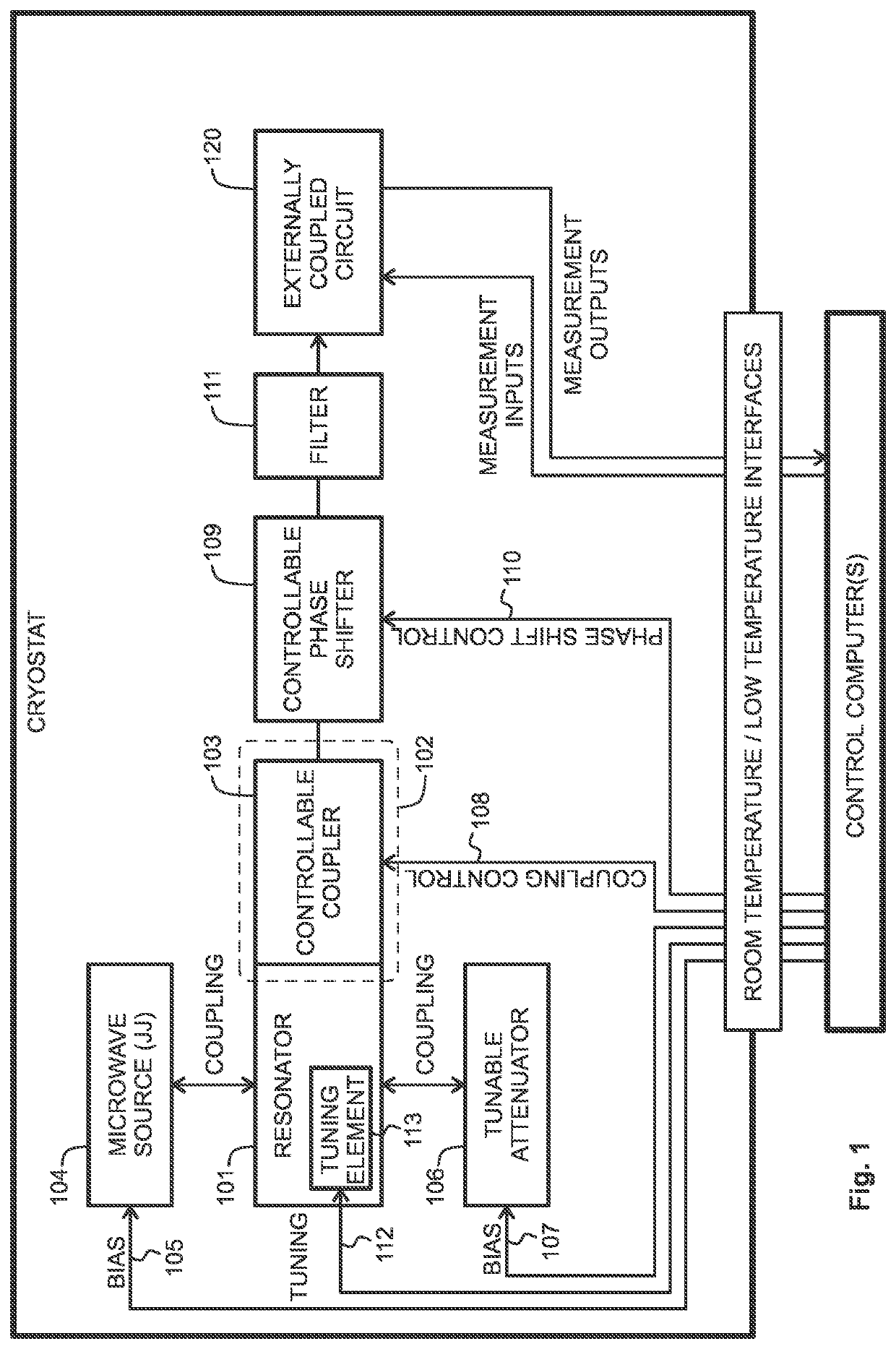
[0037]The conventional way of feeding microwave signals of controllable frequency, phase, and amplitude into a qubit or other nano-electronic circuit in a cryostat involves generating the signals at room temperature and using arrangements of transmission lines and filters to feed them inside the cryostat. The deliberately introduced attenuation that is necessary to remove thermal fluctuations also destroys a vast majority of the useful power. The efficiency of such arrangements, defined as the ratio of the eventually used power over the originally generated power, is so poor that it is not uncommon to generate the signals at well over 1 dBm a...


PUM

PropertyMeasurementUnit
plasma frequencyaaaaaaaaaa
output poweraaaaaaaaaa
thicknessaaaaaaaaaa

Abstract

A vector signal generator is capable of operating on microwave frequencies. It comprises a microwave resonator, an output for coupling microwave photons out of said microwave resonator, and a Josephson junction or junction array coupled to the microwave resonator for emitting microwave signals into the microwave resonator. A biasing circuit is provided for applying a bias to the Josephson junction or junction array. A tunable attenuator is coupled to said microwave resonator.

Description

FIELD OF THE INVENTION[0001]The invention is generally related to the technical field of generating temporally shaped signals of desired frequency, amplitude, and phase for use as controllable inputs to cryogenically cooled circuits that operate on microwave frequencies. In particular the invention is related to generating such signals inside the cryogenically cooled environment.BACKGROUND OF THE INVENTION[0002]Technologies like quantum nano-electronics and quantum computing involve the use of very special circuitry that operates at extremely low temperatures that can only be achieved with advanced cryogenic cooling techniques. Oscillating signals on microwave frequencies, in the order of some GHz or even tens or hundreds of GHz, are used as inputs to these circuits. There is thus the need to be able to generate such signals at desired frequency, amplitude, and phase. Both continuous-wave (CW) and pulsed signals may be needed. Similar needs may arise in applications that involve mat...

Claims


Application Information

Patent Timeline
Patent Type & Authority Applications(United States)
IPC IPC(8): G06N10/00H01L27/18H01B12/16H01P1/18H01P1/22H01P7/08H01L39/22
CPCG06N10/00H01L27/18H01B12/16H01L39/223H01P1/22H01P7/08H01P1/18H03B28/00H01P7/00H01P7/082H03B15/006H01P7/086B82Y10/00H10N69/00H10N60/12
Inventor GOETZ, JANMÖTTÖNEN, MIKKOHASSEL, JUHAOLLIKAINEN, TUOMAS
Owner IQM FINLAND OY
Why Eureka
Try Eureka