
Automatic valve

a technology of automatic valves and valve bodies, applied in the direction of diaphragm valves, operating means/release devices of valves, engine diaphragms, etc., can solve the problems of disadvantage of above conventional automatic valves, large pressure loss, and inability to adapt to practical us

Inactive Publication Date: 2001-12-11
ASAHI YUKIZAI KOGYO CO LTD
View PDF10 Cites 30 Cited by
  • Summary
  • Abstract
  • Description
  • Claims
  • Application Information

AI Technical Summary

Problems solved by technology

However, the above conventional automatic valve is disadvantageous as described below.
The profile of the flowing path of the conventional automatic valve is complicated, and further the flowing direction of fluid is suddenly changed, which causes a great pressure loss.
Therefore, when it is necessary to provide an automatic valve with a high flow rate, the structure of the above conventional automatic valve is not appropriate for practical use.
Further, when it is used for carrying fluid containing slurry, abrasion tends to be caused at the valve seat section, and the sealing performance is deteriorated.
Therefore, the size of the entire valve is increased, and a large space is required for installation.
Accordingly, resistance is increased in the case of operation of the valve, and it is difficult to instantly transmit the pressure of fluid to the sealing section.
Therefore, even when the valve is used for chemicals containing slurry, abrasion is seldom caused in the sealing section.

Method used


Image

  • Automatic valve
  • Automatic valve
  • Automatic valve

Examples


third embodiment

FIG. 5 is a longitudinally cross-sectional view showing the present invention. In this embodiment, the fluid communicating ports 24, 25 of the first diaphragm presser 22 and the second diaphragm presser 23 are respectively formed on the sides of the diaphragm pressers. Accordingly, the profile of the flowing path of fluid is curved. In this structure, the cylindrical body 1 and both the diaphragm pressers 22, 23 are integrated into one body by bolts and nuts. Operation of the valve of this embodiment is the same as that of the embodiment described before. Therefore, an explanation will be omitted here.

first embodiment

FIG. 6 is a longitudinally cross-sectional view showing an example of the state in which the automatic valve of the first embodiment is arranged in a piping line. In this structure, the automatic valve and the pipes are connected with each other as follows. The body caps 28, 29 to which the pipes 3031 are respectively fixed are fixed onto both sides of the automatic valve in such a manner that the cap nuts 26, 27 are screwed to the outer circumferential end sections of the cylindrical body 1 via O-rings 32, 33.


PUM


Abstract

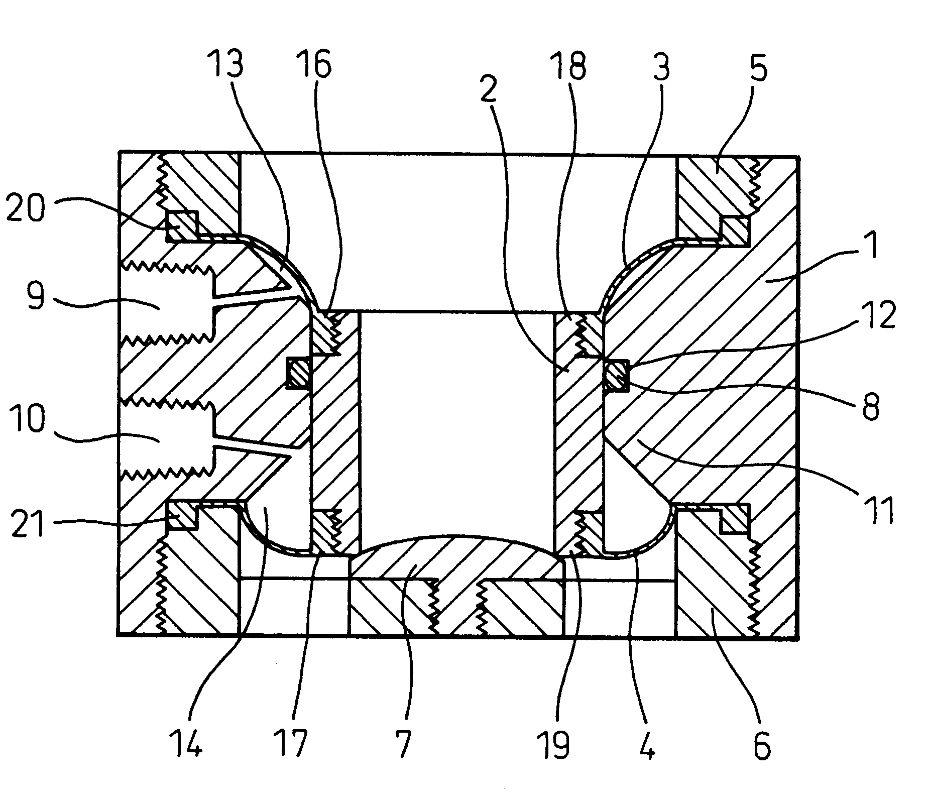
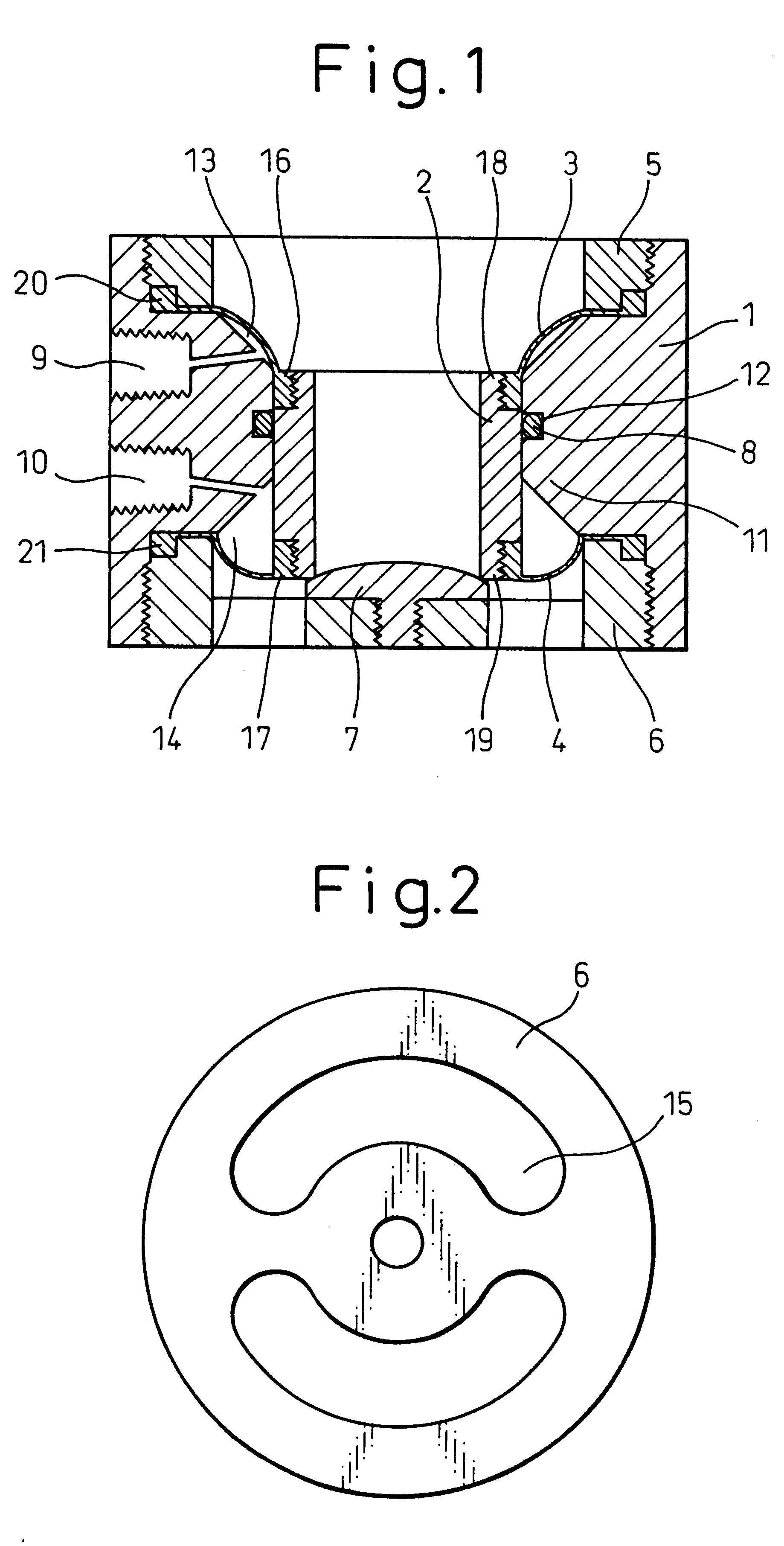
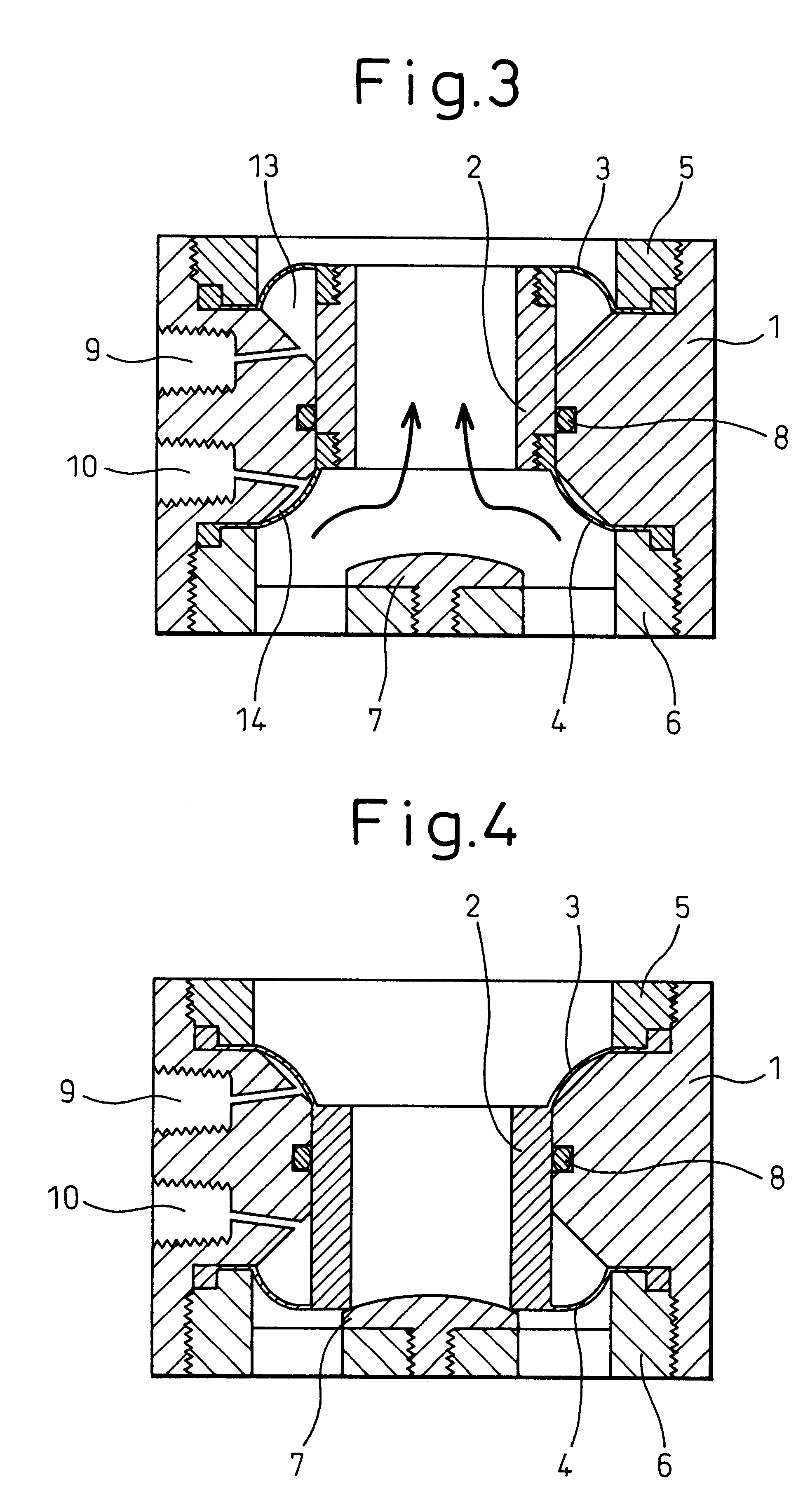
A compact automatic valve has a cylindrical body with a sleeve inserted to move in the cylindrical body in the axial direction. A first diaphragm, having an annular joint section and an annular protrusion arranged in the outer circumferential section, is joined to one end of the sleeve. A second diaphragm, having an annular joint section and an annular protrusion arranged in the outer circumferential section, is joined to the other end of the sleeve. A first cylindrical diaphragm presser, joined to one end of the cylindrical body, presses the annular protrusion of the first diaphragm and a second cylindrical diaphragm presser, joined to the other end of the cylindrical body, presses the annular protrusion of the second diaphragm. Both the first cylindrical diaphragm presser and the second cylindrical diaphragm presser have a fluid communicating port. A valve member, which is contacted with and separated from the lower end of the sleeve, is arranged at the center of the bottom of the second cylindrical diaphragm presser and alternatively contacts with or separates from the lower end of the sleeve as the sleeve moves axially to close or open the valve. A pair of fluid supply ports respectively communicate with an upper and a lower clearance formed by the cylindrical body, diaphragms and sleeve.

Description

1. Field of the InventionThe present invention relates to an automatic valve operated by a fluid. More particularly, the present invention relates to a compact automatic valve, the sealing property of which is high and the flow rate characteristic of which is excellent, which can be used for an ultra-pure water line in the semiconductor industry and also for various chemical lines in the chemical industry.2. Description of the Related ArtThe ultra-pure water line in the semiconductor industry and the various chemical lines in the chemical industry use a large number of pneumatic type automatic valves shown in FIG. 7. As shown in FIG. 7, this pneumatic type automatic valve is composed of a main body section and a drive section. The structure of the main body section is the same as that of a stop valve. That is, when the disk section and the valve seat section are contacted with and separated from each other, the valve can be opened and closed. The drive section includes a cylinder, p...

Claims


Application Information

Patent Timeline
Patent Type & Authority Patents(United States)
IPC IPC(8): F16K7/12F16K7/17
CPCF16K7/17F16K1/123
Inventor HANADA, TOSHIHIRO
Owner ASAHI YUKIZAI KOGYO CO LTD
Learn More