
Reactor system coupled to an energy emitter control circuit

a control circuit and reactor technology, applied in the direction of energy-based chemical/physical/physical-chemical processes, single pulse train generators, chemical/physical/physical-chemical processes, etc., can solve the problem of limiting the overall operating rang

Active Publication Date: 2021-08-31
LYTEN INC
View PDF3 Cites 2 Cited by
  • Summary
  • Abstract
  • Description
  • Claims
  • Application Information

AI Technical Summary

Problems solved by technology

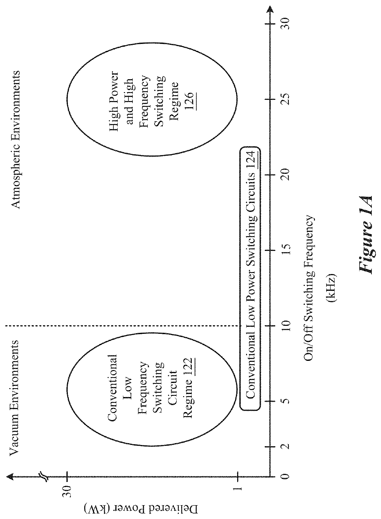
Such a circuit can be designed for a specific range of pulsing frequency, duty cycle, shape, and output power level; however, challenges encountered in traditional microwave emission device and reactor design and effectively limit overall operating range.
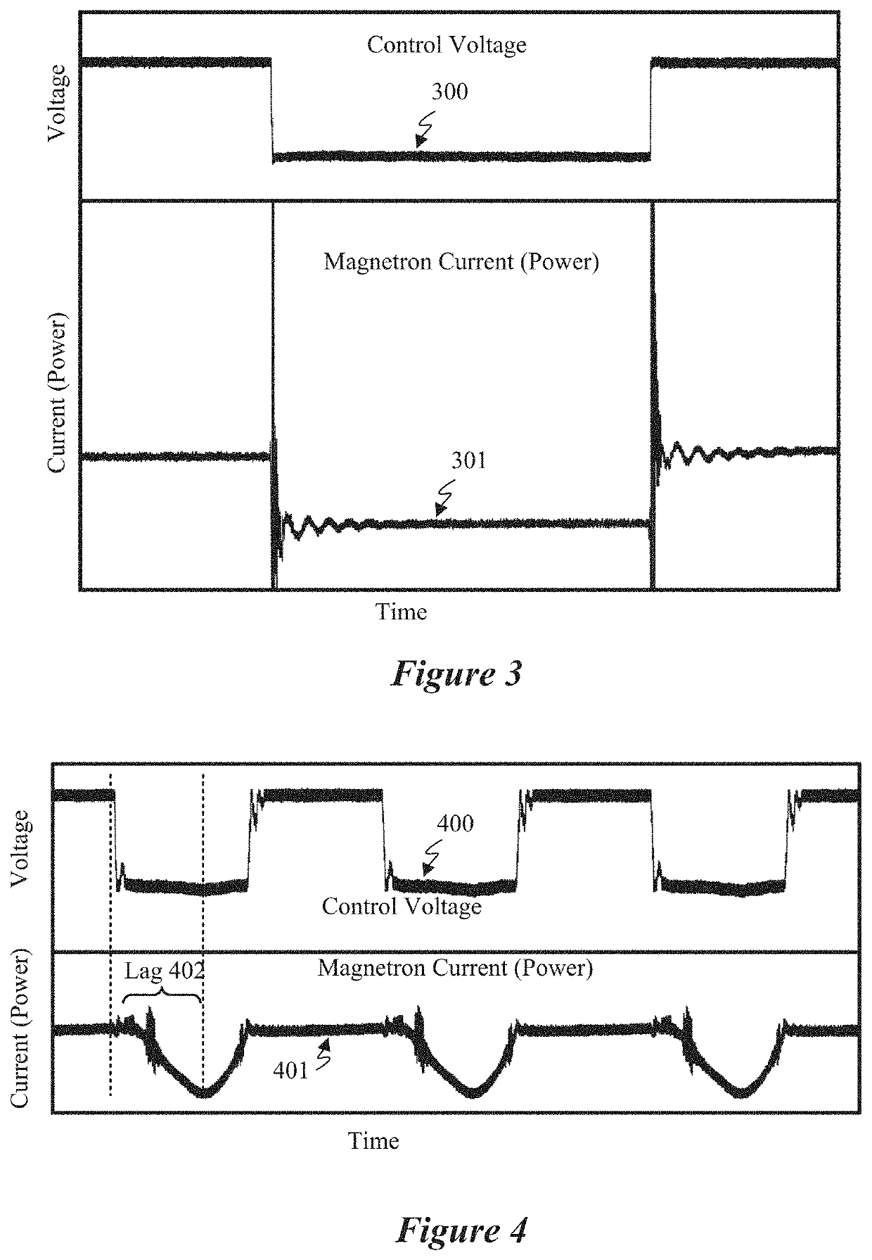
Observed rise and fall times of pulsing signals can be examples limitations observed, given that a relatively slow rise or fall time can possibly negatively impact a rate at which a signal can be switched.

Method used


Image

  • Reactor system coupled to an energy emitter control circuit
  • Reactor system coupled to an energy emitter control circuit
  • Reactor system coupled to an energy emitter control circuit

Examples


Embodiment Construction

[0034]Reference now will be made to implementations of the disclosed invention, one or more examples of which are illustrated in the accompanying drawings. Each example is provided by way of explanation of the present technology, not as a limitation of the present technology. In fact, it will be apparent to those skilled in the art that modifications and variations can be made in the present technology without departing from the scope thereof. For instance, features illustrated or described as part of one embodiment may be used with another embodiment to yield a still further embodiment. Thus, it is intended that the present subject matter covers all such modifications and variations within the scope of the appended claims and their equivalents.

[0035]Embodiments of the present systems and methods can be used for controlling, such as with a circuit, a microwave energy source to provide pulsed microwave energy for generating carbon-inclusive particles from raw materials using microwav...


PUM

PropertyMeasurementUnit
rise timeaaaaaaaaaa
rise timeaaaaaaaaaa
fall timeaaaaaaaaaa

Abstract

A microwave energy source that generates a microwave energy is disclosed. The microwave energy source has an on-state and an off-state. A control circuit is coupled to the microwave energy source and includes an output to generate a control signal that adjusts a pulse frequency of the microwave energy. A voltage generator applies a non-zero voltage to the microwave energy source during the off-state. A frequency and a duty cycle of the non-zero voltage is based on a frequency and a duty cycle of the control signal. A waveguide is coupled to the microwave energy source. The waveguide has a supply gas inlet that receives a supply gas, a reaction zone that generates a plasma, a process inlet that injects a raw material into the reaction zone, and an outlet that outputs a powder based on a mixture of the supply gas and the raw material within the plasma.

Description

CROSS-REFERENCE TO RELATED APPLICATIONS[0001]This application is a continuation-in-part of and claims priority to U.S. patent application Ser. No. 16 / 544,656 entitled “ENERGY EMITTER CONTROL CIRCUIT” filed on Aug. 19, 2019 and to U.S. patent application Ser. No. 17 / 008,188 entitled “TEMPERATURE-CONTROLLED CHEMICAL PROCESSING REACTOR” filed on Aug. 31, 2020, both of which are assigned to the assignee hereof. The disclosures of both prior Applications are considered part of and are incorporated by reference in this patent Application in their respective entireties.TECHNICAL FIELD[0002]This disclosure relates generally to a reactor for producing carbon particles, and, more particularly, to a reactor coupled to a circuit configured to propagate microwave energy at a defined pulse frequency or duty cycle into the reactor for outputting the carbon particles.DESCRIPTION OF RELATED ART[0003]Microwave emission devices such as magnetrons or klystrons, for example, can be configured to out ele...

Claims


Application Information

Patent Timeline
Patent Type & Authority Patents(United States)
IPC IPC(8): H01J37/32C01B32/205C01B32/184B01J19/12
CPCH01J37/32266B01J19/126C01B32/184C01B32/205H01J37/3277H01J37/32201H01J37/32229H01J37/32743H01J37/32788B01J2219/0801B01J2219/0875B01J2219/0894B01J2219/1206H01J2237/33H01J25/50H03B9/10H03K3/78C01B32/174C01B32/194B01J2219/1269B01J19/088B01J19/085B01J2219/1281H01J23/00H01J25/00
Inventor STOWELL, MICHAEL W.PHAM, TUNG VANANZELMO, BRYCE H.RISO, THOMAS
Owner LYTEN INC
Learn More