
Laser processing apparatus and laser processing method

a laser processing and laser processing technology, applied in metal-working equipment, welding equipment, manufacturing tools, etc., can solve the problems of insufficient melting of workpieces, insufficient thermal lens effect, and inability to recognize characters, so as to reduce installation footprint, reduce equipment investment costs, and suppress thermal lens effect

Active Publication Date: 2021-08-24
FUJIKURA LTD
View PDF16 Cites 1 Cited by
  • Summary
  • Abstract
  • Description
  • Claims
  • Application Information

AI Technical Summary

Benefits of technology

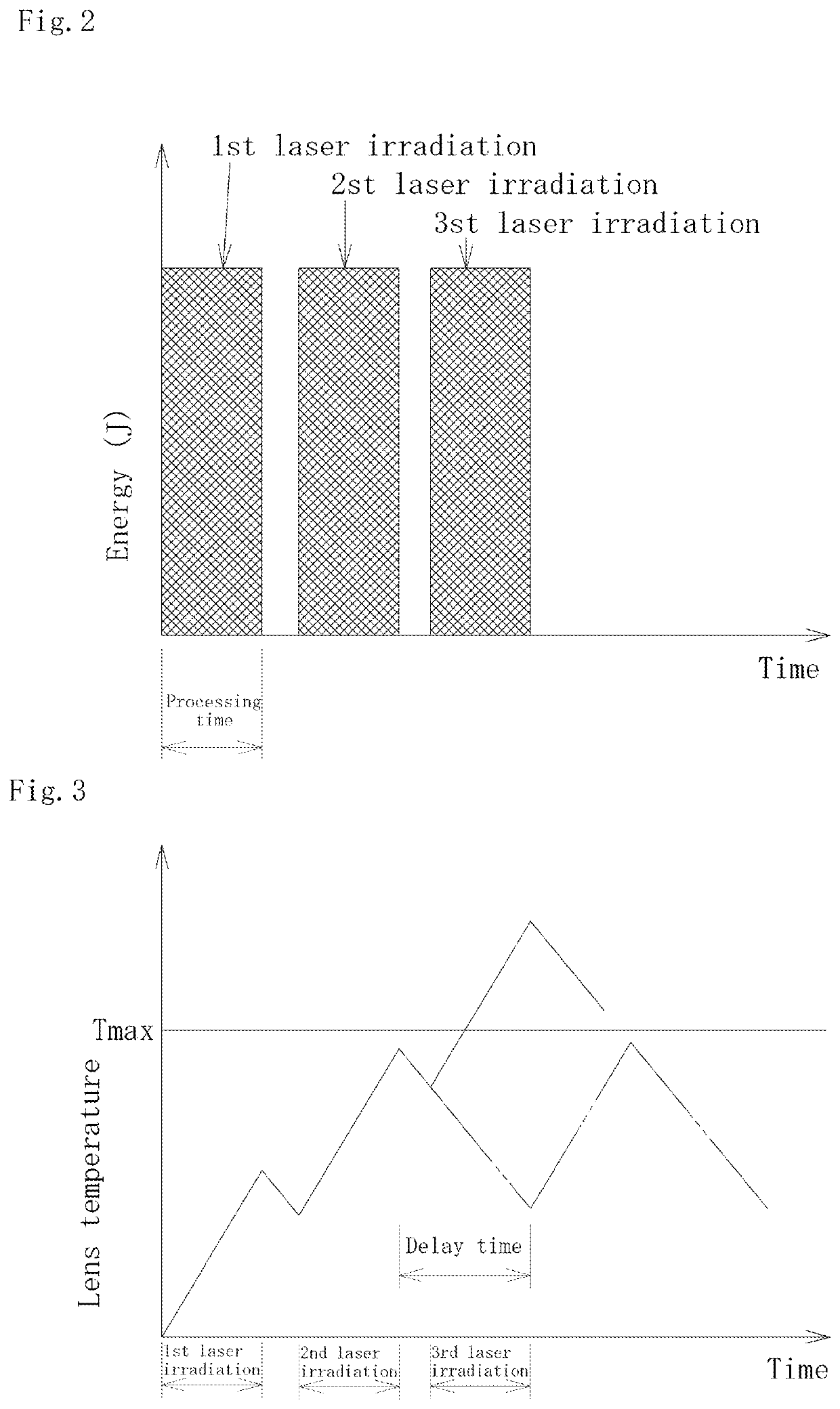
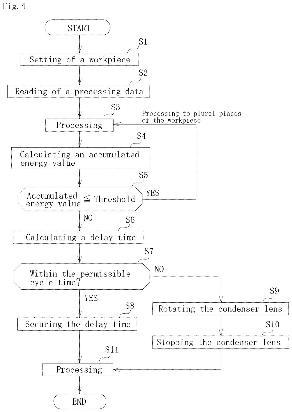
The present invention provides a laser processing apparatus and method that can perform different types of processing, such as welding and marking, with a single apparatus. The apparatus calculates energy values for each processing and sets a delay time between them to allow for sufficient cooling of the lens to prevent thermal effects. This results in a reduction in equipment investment costs and installation footprint. The apparatus can also position itself for multiple types of processing, reducing processing time. Additionally, the apparatus can record processing information, such as marking lot numbers, for increased traceability accuracy.

Problems solved by technology

However, the YAG pulsed laser has a low repetition frequency of 30 Hz or less, and scanning at high speeds results in distant processing marks (dots), which cannot be recognized as characters.
Hence, the YAG pulsed laser is not suitable for surface processing, e.g., marking (printing) or patterning.
Therefore, the laser radiation is completed before heat is transferred to a workpiece, resulting in insufficient melting of the workpiece.
The Q-switched laser is therefore not suitable for material processing, e.g., welding.
The resultant problem is increased costs.
However, with a continuous-wave laser, heat accumulation due to continuous laser beam incidence on a condenser lens can be increased excessively, causing the thermal lens effect and a reduction in processing quality.
The change of the focal position increases a spot diameter at a processing point, which reduces the value of the power density (laser power output / cross-sectional area of spot), resulting in a welding defect or a defective character in the case of marking.
However, a condenser lens made of synthetic quartz glass is very expensive.
Thus, there is a drawback that spatter, fume or the like generated during laser processing fouls the lens and the absorption of a laser beam once generated increases the thermal lens effect.

Method used


Image

  • Laser processing apparatus and laser processing method
  • Laser processing apparatus and laser processing method
  • Laser processing apparatus and laser processing method

Examples


Embodiment Construction

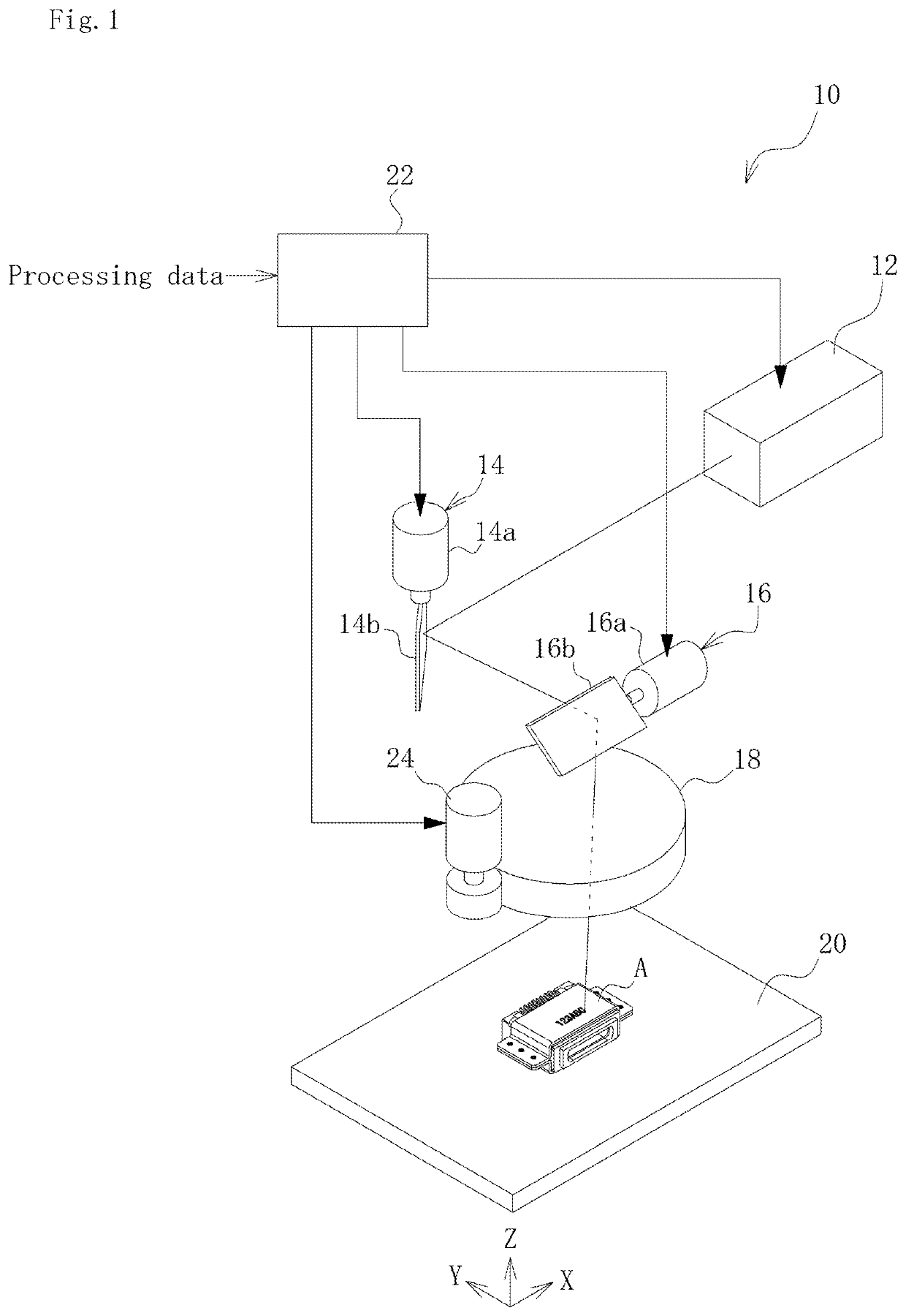
[0026]An embodiment of the present invention is described in detail below on the basis of the drawings. FIG. 1 is a schematic configurational view of a laser processing apparatus according to an embodiment of the present invention.

[0027]As illustrated in FIG. 1, a laser processing apparatus 10 according to the present embodiment includes a continuous-wave laser oscillator 12, an X-axis galvano scanner 14, a Y-axis galvano scanner 16, a condenser lens 18, a stage 20 on which a workpiece A is fixed in position, and a control device 22.

[0028]The continuous-wave laser oscillator 12 emits a continuous-wave laser beam used for laser processing (hereinafter also simply referred to as the “laser beam”) toward the galvano scanners 14 and 16. The continuous-wave laser oscillator 12 may, for example, be a continuous-wave fiber laser of a single-mode light propagation mode having a wavelength of 1000 to 1100 nm.

[0029]The X-axis galvano scanner 14 and the Y-axis galvano scanner 16 are cooperated...


PUM

PropertyMeasurementUnit
repetition frequencyaaaaaaaaaa
wavelengthaaaaaaaaaa
energyaaaaaaaaaa

Abstract

A laser processing apparatus 10 includes a continuous-wave laser oscillator 12 for generating a continuous-wave laser beam, a condenser lens 18 for concentrating a continuous-wave laser beam onto a workpiece, and a delay time setting means for calculating an energy value for each processing by a continuous-wave laser beam irradiation on the basis of processing data and accumulating the calculated energy value, and setting a predetermined delay time between the processings when the accumulated energy value exceeds a predetermined threshold.

Description

TECHNICAL FIELD[0001]The present invention relates to a laser processing apparatus including a continuous-wave laser oscillator for generating a continuous-wave laser beam and a condenser lens for concentrating the continuous-wave laser beam onto a workpiece, and irradiating the workpiece with the continuous-wave laser beam multiple times according to processing data to perform processing multiple times, and a laser processing method.BACKGROUND ART[0002]Examples of lasers include pulsed lasers that intermittently emit a high-power laser beam and continuous-wave lasers that continuously emit a laser beam. The pulsed laser is good at different types of processing depending on the length of pulse width or the level of repetition frequency. The YAG pulsed laser, for example, has a relatively large pulse width of 0.2 ms to 10 ms and is capable of sufficiently transferring heat to a workpiece to reliably melt the workpiece. Therefore, the YAG pulsed laser is suitable for macroscopic mater...

Claims


Application Information

Patent Timeline
Patent Type & Authority Patents(United States)
IPC IPC(8): B23K26/0622B23K26/22B23K26/06B23K26/082B23K26/21
CPCB23K26/22B23K26/0622B23K26/0626B23K26/0648B23K26/082B23K26/21B23K26/064B23K26/00
Inventor YAMAGISHI, HIROYUKINAMBA, TOSHITAKA
Owner FUJIKURA LTD
Learn More