
Method and device for detecting faults in a transmission line

a transmission line and fault technology, applied in the field of system diagnostic of wires, can solve the problems of generating discontinuities in the parameters per unit length of cables, affecting so as to increase the accuracy of detection, increase the operating life of devices, and increase the effect of measurement precision

Active Publication Date: 2021-07-06
COMMISSARIAT A LENERGIE ATOMIQUE ET AUX ENERGIES ALTERNATIVES
View PDF8 Cites 0 Cited by
  • Summary
  • Abstract
  • Description
  • Claims
  • Application Information

AI Technical Summary

Benefits of technology

[0012]Advantageously, the method of the invention is a method for directly processing information output from an analogue-digital converter of a reflectometry analyzing system, that allows a stationary signal to be analyzed without post-processing being required to recompose it.
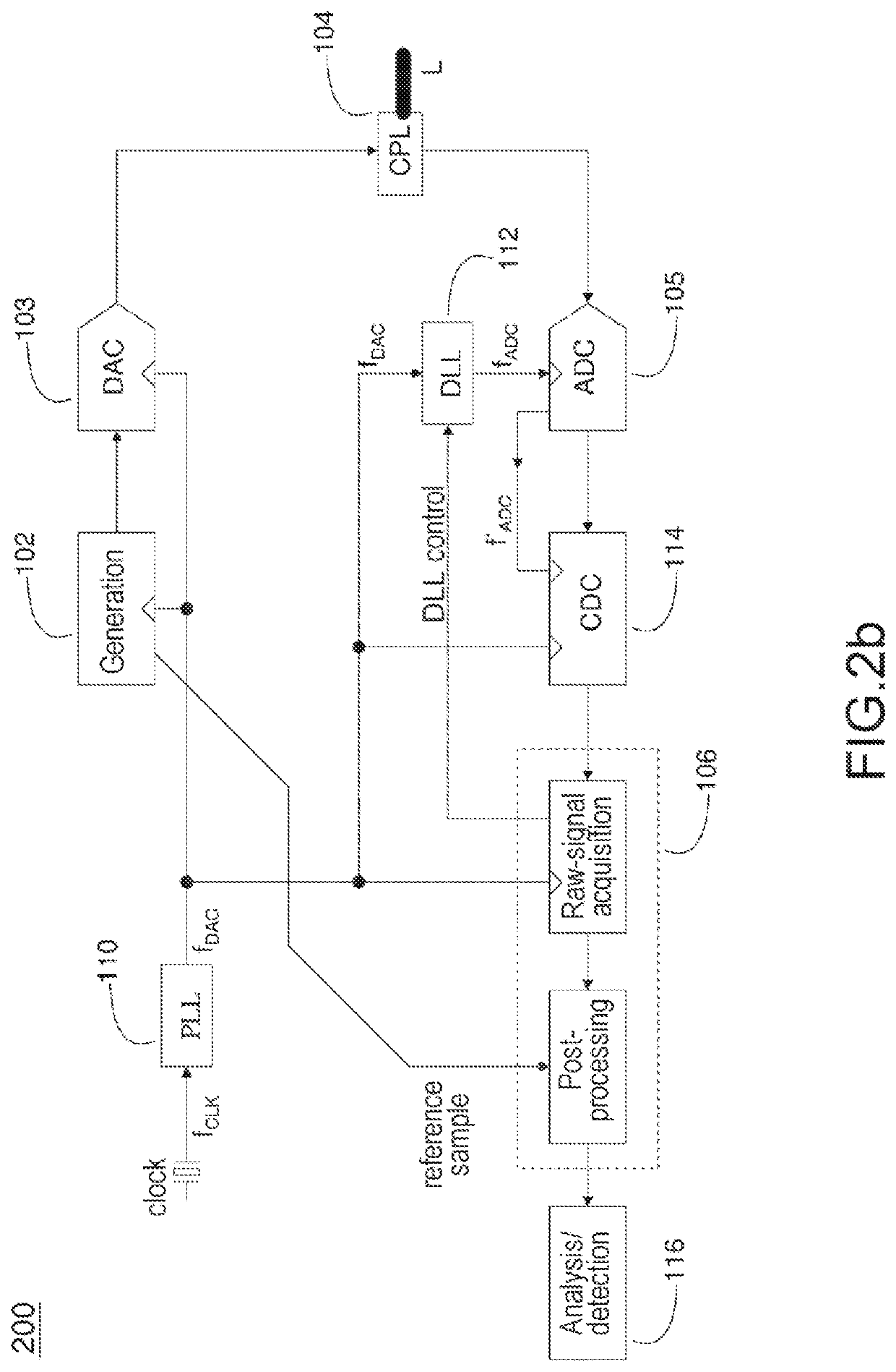
[0013]Advantageously, the device of the invention allows the DAC and ADC converters to operate asynchronously.
[0014]The present invention is advantageously applicable to on-board electronic systems in which, miniaturization being a challenge, it is recommendable to limit the number of components and power consumption in order to increase the operating lifetime of devices. Thus, the present invention has the advantage of providing a low-cost solution while increasing the precision of the measurements, and is in particular applicable to the detection of intermittent faults (of short duration), something that current applications are unable to do because of their narrow bandwidth.
[0015]Advantageously, the present invention allows the precision of detection to be increased, and thus intermittent faults that are not detectable with existing systems to be observed.
[0018]the throughput of digital communications to be increased via the faster synchronization and longer acquisition times enabled;

Problems solved by technology

These cables are subject to the same stresses as the systems that they connect and may be subject to failures.
Such a break most often results from a fault that modifies the characteristic impedance of the cable locally, thereby generating a discontinuity in its parameters per unit length.
One major drawback of this method is that it requires a very long acquisition time and data processing that is complex.
However, this delay may be unacceptable when it is a question of detecting intermittent faults (a short-circuit for example) the duration of which is short.
Moreover, the means required to implement this method, and in particular to generate the phase shifts of the clock signal, are expensive.
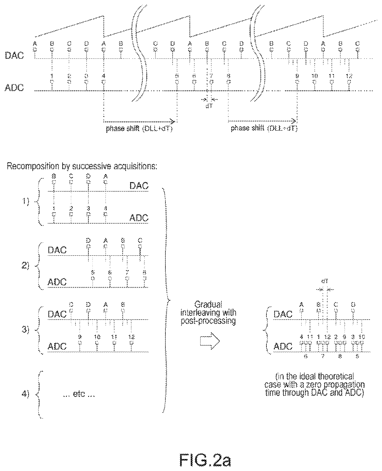
Furthermore, the precision of the measurements must meet over-sampling rules, and this method requires resource-intensive post-processing of the data to be carried out to recompose the over-sampled signal.
This constraint is all the more complex to meet when analogue components are used to generate the delays, these analogue components being components such as delay-locked loops (DLL), which are moreover liable to introduce parasitic frequencies, but also converters or filters.
However, very-high-performance analogue-digital converters able to inject and measure a high-frequency sampling signal remain expensive.
They are therefore unsuitable for low-cost systems or for methods such as the aforementioned consisting in increasing the number of components.

Method used


Image

  • Method and device for detecting faults in a transmission line
  • Method and device for detecting faults in a transmission line
  • Method and device for detecting faults in a transmission line

Examples


Embodiment Construction

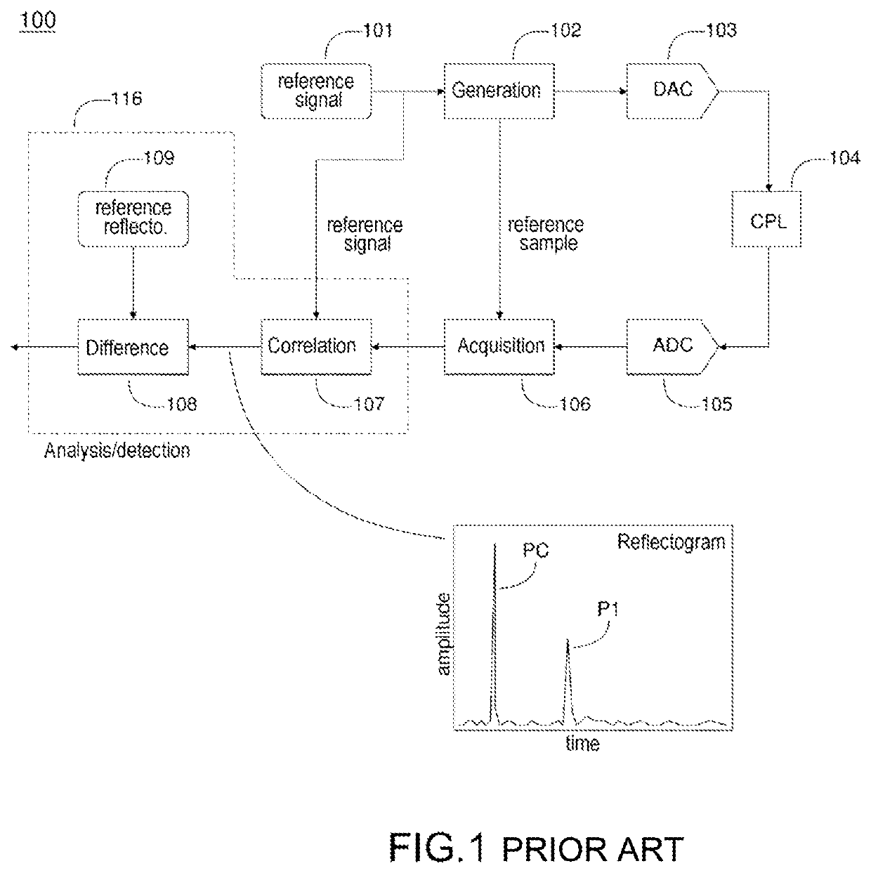
[0045]FIG. 1 schematically shows a known prior-art system 100 for detecting faults in a transmission line, according to the principle of analysis by reflectometry. The system 100 mainly comprises an emitting portion consisting of a generator 102 for generating a reference or test signal, based on parameters 101 of the signal. The reference signal may be time-domain or frequency-domain. It may be a question of a simple time-domain pulse or of a more elaborate signal, provided that the latter has good autocorrelation properties, i.e. that the result of an autocorrelation computation applied to this signal gives a significant amplitude peak that it is possible to identify and to detect. For example, the signal used may be an OMTDR (orthogonal multitone time-domain reflectometry) or MOTOR (multicarrier time-domain reflectometry) signal. The signal is sent to a digital-analogue converter (DAC) 103 that allows the digital reference signal to be converted into an analogue signal that is th...


PUM


Abstract

A method and device for detecting faults in a transmission line by reflectometry, include the following steps: injecting into the transmission line a reference signal at an emission frequency fDAC; collecting a reflected signal at a point on the transmission line; sampling the reflected signal at a sampling frequency fADC, the sampling frequency fADC being different from the emission frequency fDAC; storing each point of the sampled signal at a memory address corresponding to an index assigned to the point of the sampled signal and according to a precomputed memory-address increment Δ, the memory-address increment Δ depending on the emission frequency fDAC, on the sampling frequency fADC, on an over-sampling factor Ω and on a preset acquisition time Σ; repeating the storing step during the acquisition time Σ; and generating, from the points stored during the acquisition time, a recomposed signal able to be used to detect faults.

Description

CROSS-REFERENCE TO RELATED APPLICATIONS[0001]This application is a National Stage of International patent application PCT / EP2018 / 064414, filed on Jun. 1, 2018, which claims priority to foreign French patent application No. FR 1755478, filed on Jun. 16, 2017, the disclosures of which are incorporated by reference in their entirety.FIELD OF THE INVENTION[0002]The invention relates to the field of systems for diagnosing wires based on the principle of reflectometry. One subject of the invention is in particular a method for detecting faults in a transmission line, such as a cable.BACKGROUND[0003]Cables for supplying power or transmitting information are ubiquitous in all electrical systems. These cables are subject to the same stresses as the systems that they connect and may be subject to failures. It is therefore necessary to be able to analyze their state and to obtain information on not only whether or not there are any faults but also on their location and their type, in order to ...

Claims


Application Information

Patent Timeline
Patent Type & Authority Patents(United States)
IPC IPC(8): G01R31/08G01R31/11
CPCG01R31/11
Inventor LAYER, CHRISTOPHECABANILLAS, ESTEBANDUPRET, ANTOINE
Owner COMMISSARIAT A LENERGIE ATOMIQUE ET AUX ENERGIES ALTERNATIVES
Learn More