
Method of treating high strength wastewater by anaerobic bio reactor

a bioreactor and high-strength technology, applied in biological water/sewage treatment, cell components, membranes, etc., to achieve the effect of low operating cos

Active Publication Date: 2021-05-18
AQUATECH INT LLC
View PDF1 Cites 0 Cited by
  • Summary
  • Abstract
  • Description
  • Claims
  • Application Information

AI Technical Summary

Benefits of technology

[0018]The ceramic membrane demonstrated good tolerance at high temperature operation and tolerated variable pH conditions during cleaning. It also provided good mechanical strength to operate at high Trans Membrane Pressure (TMP). The thermophilic process has shown improved biogas generation as compare to mesophilic. The mass balance data showed methanogenesis in the range of 50 to 90% for mesophilic range and up to 94% for thermophilic range.
[0021]1. An integrated Anaerobic process which combines highly efficient aneaerobic reactor delivering high COD treatment for high strength waste water with almost quantitative methane gas yields combined with a robust and non fouling membrane system.
[0022]2. A uniquely designed hydraulic mixer which makes sure that reactor is kept continuously mixed even at high MLSS concentration while maintain the sludge to provide a highly reactive environment and adjusting the particle size such that it remains non fouling for membranes and leakage through the membranes remains negligible.
[0024]4. A robust membrane system design which provides order of magnitude higher flux as compared to polymeric membranes, can withstand high temperature process operation and still remain fouling resistant and can be cleaned with aggressive chemical cleaning compounds including oxidizing agents.
[0025]5. Integration with a unique post treatment which is easy to operate, delivers product without adding any suspended solid contamination and has the potential to deliver additional energy from the process.

Problems solved by technology

These include, for example, fouling of membrane, limitation of polymeric membranes, operation at high temperature especially in thermophilic range, sensitivity of polymeric membranes to certain oxidizing agents or biological activities, limitation of membrane to handle aggressive chemical cleaning and mechanical properties to deal with high concentration of organic or inorganic suspended solids.

Method used


Image

  • Method of treating high strength wastewater by anaerobic bio reactor
  • Method of treating high strength wastewater by anaerobic bio reactor
  • Method of treating high strength wastewater by anaerobic bio reactor

Examples


example-1

Study with Glucose Water

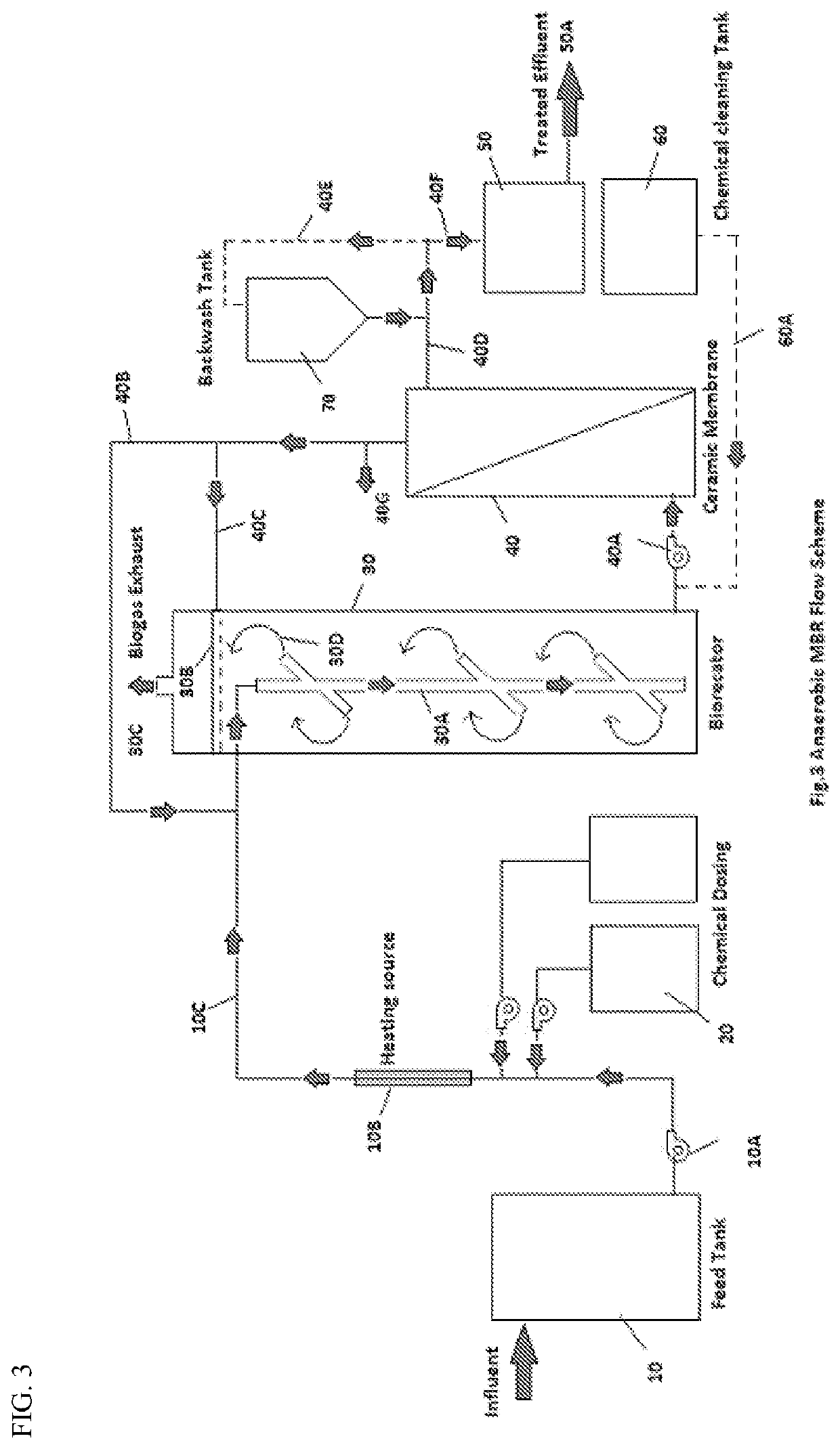
[0072]In this part of the study reactor was run with simulated water having glucose as contributor of COD and BOD and other constituent for alkalinity, TDS and macro / micro nutrient balance. The System was run as per the flow scheme shown in FIG. 3. This was the initial phase of study so reactor was operated at low organic loading by controlling flux through the membrane. Initially reactor was operated at 5000 mg / lit feed COD and then gradually this COD is increased to 15000 mg / lit. With increasing feed COD there was gradual increase in reactor HRT. Gradually HRT of reactor was increased to 70 hours from 32 hours initially. This was done to maintain organic loading of the reactor and avoid shock loading during start up time. With increase of COD there was increase in MLSS also and it increased to 25000 mg / lit at the feed COD of 14000 mg / lit. During the trial COD loading of the reactor was in the range of 3.4 to 4.2 Kg / m3·day.

[0073]

TABLE 1HRTMLSSFeed CODCOD Red...

example-2

Study with Dairy Wastewater

[0079]Study of dairy wastewater was conducted with the similar flow scheme as shown in FIG. 3. Reactor temperature was kept at 37° C., which is in the mesophilic range. Simulated water having dairy wastewater was used as feed. Micronutrients were added to the feed water. Composition of the wastewater is shown in Table 4.

[0080]

TABLE 4composition of dairy wastewaterComponent% ContributionCarbohydrates52.3Proteins6.6Sugar34.9Fat6.2

[0081]With dairy wastewater, system was operated for 123 days continuously. Stable reactor performance has been observed and COD reduction was maintained at 98% as shown FIG. 7.

[0082]Mass balance for dairy wastewater was done to understand the progress in terms of hydrolysis, acidification and Methanogenesis.

[0083]Details are tabulated in Table 5.

[0084]

TABLE 5ParametersUnitValueAverage gas generation per Kg of CODM3 / Kg / day0.26% Hydrolysis%68.00% Acidification%72.84% Methanogenesis%67.76

[0085]Gas generation in case of dairy waste tri...

example-3

Study with Brewery Wastewater

[0086]This process was studied with simulated brewery wastewater having 6000-ppm average feed COD. During acclimatization phase the reactor was fed with simulated wastewater. Same flow scheme was followed as shown in FIG. 3. It took almost 50 days to achieve 98% COD reduction from the system after changing feed water character. Composition of feed water is shown in

[0087]

TABLE 6NameConc, ppmSolutionAmmonium Sulphate11Nitrogen sourceDisodium hydrogen phosphate140Phosphate source &bufferEthanol3.54C-sourceMalt extract1000C-sourceMaltose860C-sourcePeptone150C-sourceYeast extract500C-source

[0088]For the initial few days the reactor was operated at HRT of 70 hours to stabilize the system and after that HRT was gradually reduced to 30 hours. Then operated at 30 hours HRT and 5 Kg COD loading. At this condition reactor shows 98% COD reduction. COD reduction was observed to be maintained during continuous trial of 100 days.

[0089]Mass balance study for this trial ...


PUM

PropertyMeasurementUnit
temperatureaaaaaaaaaa
velocityaaaaaaaaaa

Abstract

We provide methods, systems, and apparatus for treatment of high chemical oxygen demand wastewater using anaerobic treatment with ceramic membranes. We also provide post-treatment using microbial fuel cells.

Description

CROSS-REFERENCE TO RELATED APPLICATIONS[0001]This application claims priority to Indian Patent Application No. 201611036169, filed on Oct. 21, 2016. That application is incorporated by reference herein.BACKGROUND OF THE INVENTIONField of the Invention[0002]Embodiments relate to the treatment of high strength wastewater by anaerobic processing. Ceramic membranes are also incorporated into the treatment.Background of the Related Art[0003]Anaerobic treatment has been used for treatment of concentrated industrial wastewater as well as domestic waste water (See “Comparisons between the UASB and the EGSB Reactor,” Seung J. Lim). Jewel (1987) reported that the septic tank was the simplest, the oldest and most widely used process.[0004]Anaerobic treatment is an energy generating process, in contrast to the aerobic systems that generally demands high-energy inputs for aeration purpose. It is relatively simple and inexpensive technology that consumes less energy, space and produces less exces...

Claims


Application Information

Patent Timeline
Patent Type & Authority Patents(United States)
IPC IPC(8): C02F3/28B01D61/18B01D65/02B01D71/02C02F3/00H01M4/96H01M8/16B01D61/14
CPCC02F3/2853B01D61/18B01D65/02B01D71/024C02F3/005H01M4/96H01M8/16B01D61/14B01D2311/10B01D2311/2688B01D2315/06B01D2315/10B01D2321/04B01D2321/168B01D2321/2041C02F2303/12C02F2303/16Y02E60/50
Inventor CHIDAMBARAN, RAVIRAINA, PAVANCHANDAN, NITINCHAWANDE, SNEHA SURYAKANT
Owner AQUATECH INT LLC
Learn More