Magnetic recording medium and magnetic storage apparatus
a magnetic recording medium and recording medium technology, applied in the field of magnetic recording medium and magnetic storage apparatus, can solve the problems of easy recording bleeding and decrease in the snr of the magnetic recording medium, and achieve the effect of high snr
- Summary
- Abstract
- Description
- Claims
- Application Information
AI Technical Summary
Benefits of technology
Problems solved by technology
Method used
Image

Examples
example 1
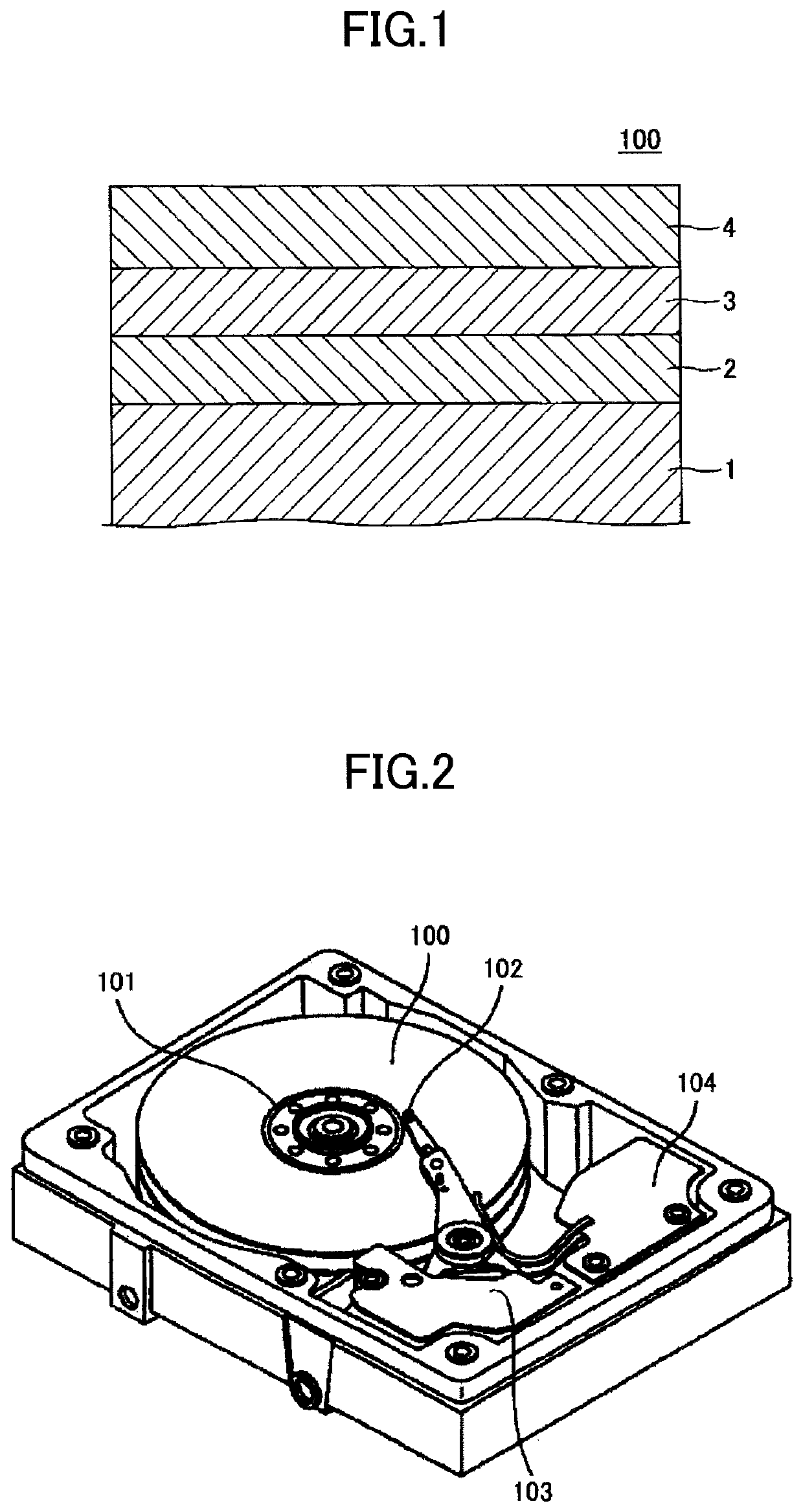
[0082]First, an underlayer was deposited on a glass substrate having a diameter of 2.5 inches. Specifically, a 50Co-50Ti film having a film thickness of 50 nm was deposited on the 2.5-inch glass substrate, as a first underlayer, and the glass substrate was thereafter heated at 300° C., where the “50Co-50Ti film” represents an alloy of 50 at % Co and 50 at % Ti, and similar representations are used hereinafter. Next, a 80Cr-20V film having a film thickness of 12 nm was deposited as a second underlayer. Further, a W film having a film thickness of 40 nm was deposited as a third underlayer, and a MgO film having a film thickness of 3 nm was deposited as a fourth underlayer. Note that a DC magnetron sputtering apparatus was used to deposit the first through fourth underlayers, and Ar was used as a sputtering gas.
[0083]Thereafter, the glass substrate was heated at 520° C. Next, a magnetic layer having a thickness of 2 nm was deposited on the underlayer (including the first through fourth...
example 2
[0087]The magnetic recording medium of Example 2 was manufactured similarly to the magnetic recording medium of Example 1, except that the sputtering target 2 was used in place of the sputtering target 1.
[0088]Upon using an infrared spectrometer (IR) to analyze the magnetic layer, it was found from the presence of a peak of B—H stretching vibration that the magnetic layer included hydrogen-containing amorphous boron (a-B:H). Also, from the intensity of the peak of B—H stretching vibration and the intensity of the peak of B—B stretching vibration, the content of a-B:H and the content of non-hydrogenated boron in the magnetic layer were respectively determined as 10% by volume and 30% by volume.
[0089]Upon using an X-ray diffraction (XRD) apparatus to analyze the underlayer and the magnetic layer, it was confirmed that the underlayer was a (100)-oriented film having a BCC structure, and that the magnetic layer was a (001)-oriented film having a L10 structure.
example 3
[0090]The magnetic recording medium of Example 3 was manufactured similarly to the magnetic recording medium of Example 1, except that the sputtering target 3 was used in place of the sputtering target 1.
[0091]Upon using an infrared spectrometer (IR) to analyze the magnetic layer, it was found from the presences of peaks of B—H stretching vibration and N—H stretching vibration that the magnetic layer included hydrogen-containing amorphous boron nitride (a-BN:H). Also, from the intensities of the peaks of B—H stretching vibration and N—H stretching vibration and the intensity of the peak of B—N stretching vibration, the content of a-BN:H and the content of non-hydrogenated boron nitride in the magnetic layer were respectively determined as 10% by volume and 30% by volume.
[0092]Upon using an X-ray diffraction (XRD) apparatus to analyze the underlayer and the magnetic layer, it was confirmed that the underlayer was a (100)-oriented film having a BCC structure, and that the magnetic lay...
PUM
| Property | Measurement | Unit |
|---|---|---|
| thickness | aaaaa | aaaaa |
| thickness | aaaaa | aaaaa |
| thickness | aaaaa | aaaaa |
Abstract
Description
Claims
Application Information
 - R&D
- Intellectual Property
- Life Sciences
- Materials
- Tech Scout
- Unparalleled Data Quality
- Higher Quality Content
- 60% Fewer Hallucinations
Browse by: Latest US Patents, China's latest patents, Technical Efficacy Thesaurus, Application Domain, Technology Topic, Popular Technical Reports.
© 2025 PatSnap. All rights reserved.Legal|Privacy policy|Modern Slavery Act Transparency Statement|Sitemap|About US| Contact US: help@patsnap.com