
System and method for phase-contrast MRI with hybrid one-and two-sided flow encoding and velocity spectrum separation (HOTSPA)

a phase-contrast and flow encoding technology, applied in the field of system and method for phase-contrast mri with hybrid, can solve the problems of not always feasible to determine if a stenosis, not always accurate or sufficient, and the contrast agent that must be administered to enhance the blood vessel carries a significant financial cost, so as to reduce the temporal sampling period and temporal footprint, and sample the hybrid m1-t space more efficiently.

Active Publication Date: 2021-04-13
RGT UNIV OF CALIFORNIA
View PDF6 Cites 0 Cited by
  • Summary
  • Abstract
  • Description
  • Claims
  • Application Information

AI Technical Summary

Benefits of technology

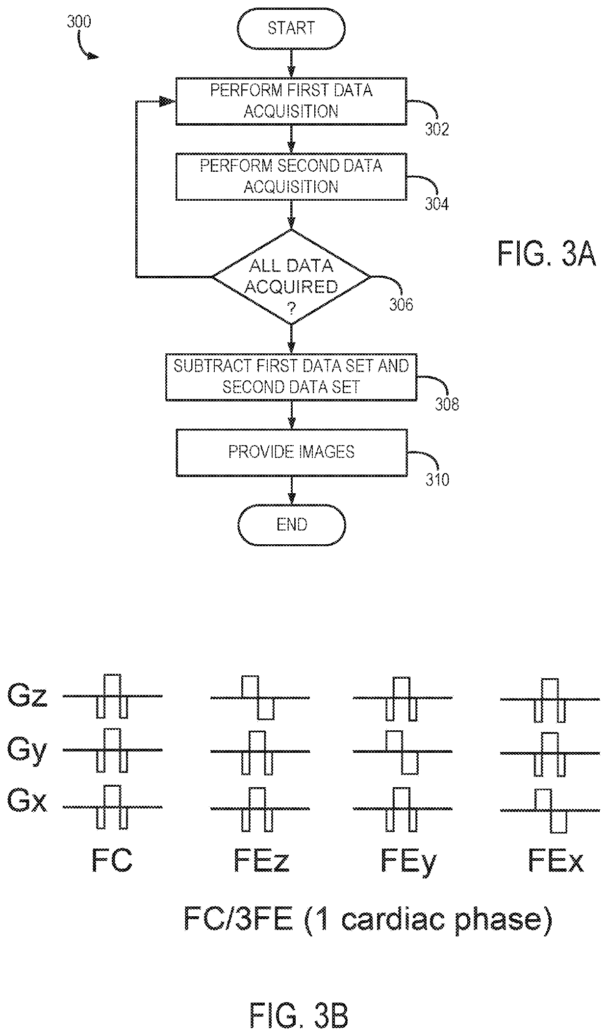
The present patent provides a system and method for performing flow or velocity encoded magnetic resonance imaging (MRI) using a hybrid one- and two-sided flow encoding and velocity spectrum separation, referred to as the HOTSPA technique. This technique allows for more efficient sampling of the hybrid M1-t space and reduces the temporal sampling period and temporal footprint of 4D flow acquisition by, for example, 50 percent compared to conventional PC-MRI. The HOTSPA technique also enables separations of the Fourier velocity spectrum of the background phase (FC) waveform, as well as the velocity waveforms in the three FE directions, such as within the cardiac cycle. Compared to conventional PC-MRI, the HOTSPA technique can sample the hybrid M1-t space more efficiently.

Problems solved by technology

While CE MRA is a highly effective means for noninvasively evaluating the vascular and physiological performance, for example, by studying perfusion, the technique suffers from several additional drawbacks.
First, the contrast agent that must be administered to enhance the blood vessel carries a significant financial cost.
Second, contrast agents such as gadolinium have recently been shown to be causative of a debilitating and potentially fatal disorder called nephrogenic systemic fibrosis (NSF).
Third, CE MRA, may not provide accurate or sufficient hemodynamic information, so that it is not always feasible to determine if a stenosis is hemodynamically significant or to assess the perfusion in a clinically useful manner.
For these applications, the temporal resolution is typically poorer than conventional 2D PC-MRI due to the need to acquire the FC data and FE data in three directions for each cardiac phase.
Low temporal resolution and long temporal footprint can result in under-estimation of the maximum peak velocity as well as pressure gradients across valves or stenoses.
However, doing so it requires increased total image acquisition time.
However, the temporal footprint of each cardiac phase in the SVE technique is the same as traditional 2D PC-MRI, despite improved temporal resolution through view-sharing.

Method used


Image

  • System and method for phase-contrast MRI with hybrid one-and two-sided flow encoding and velocity spectrum separation (HOTSPA)
  • System and method for phase-contrast MRI with hybrid one-and two-sided flow encoding and velocity spectrum separation (HOTSPA)
  • System and method for phase-contrast MRI with hybrid one-and two-sided flow encoding and velocity spectrum separation (HOTSPA)

Examples


example

[0076]An example study was performed on a 3T scanner with a 4-channel neck (in vivo studies) coil. As used in this study, “mean flow velocity” means the average velocity within the entire blood vessel lumen. Also, “peak velocity” means the maximum velocity within the entire blood vessel. Further, “magnitude velocity” means the square root of sum of squares of 3D velocities (=√{square root over (Vx2+Vy2+Vz2)}). The magnitude mean flow velocity can be used to indicate the average magnitude velocity within the entire blood vessel lumen, and magnitude peak velocity can be used to indicate the maximum magnitude velocity within the entire blood vessel lumen. Finally, “maximum velocity” means the maximum velocity within the entire cardiac cycle. This often happens in the peak systolic cardiac phases.

Retrospective In Vivo Study (2D)

[0077]The commons carotid arteries (CCAs) of six volunteers were scanned using a 2D PC-MRI sequence with 3 FE directions (FC / 3FE). The sequence parameters includ...


PUM

PropertyMeasurementUnit
angleaaaaaaaaaa
velocityaaaaaaaaaa
peak velocityaaaaaaaaaa

Abstract

A system and method is provided for acquiring flow encoded data from a subject using a magnetic resonance imaging (MRI) system. The method includes acquiring flow encoded (FE) data with alternating encoding polarities and along two of three orthogonal directions through the subject over at least two cycles of the flow within the subject; and separating the FE data into directional FE datasets using a temporal filter that separates the FE data based on temporal modulation of the FE directions caused by the alternating encoding polarities extending over the at least two cycles of the flow within the subject that shift the Fourier spectrum of velocity waveforms corresponding to the FE data. The method also includes using the directional FE datasets to generate an image of the subject showing flow within the subject caused by the at least two cycles of flow within the subject.

Description

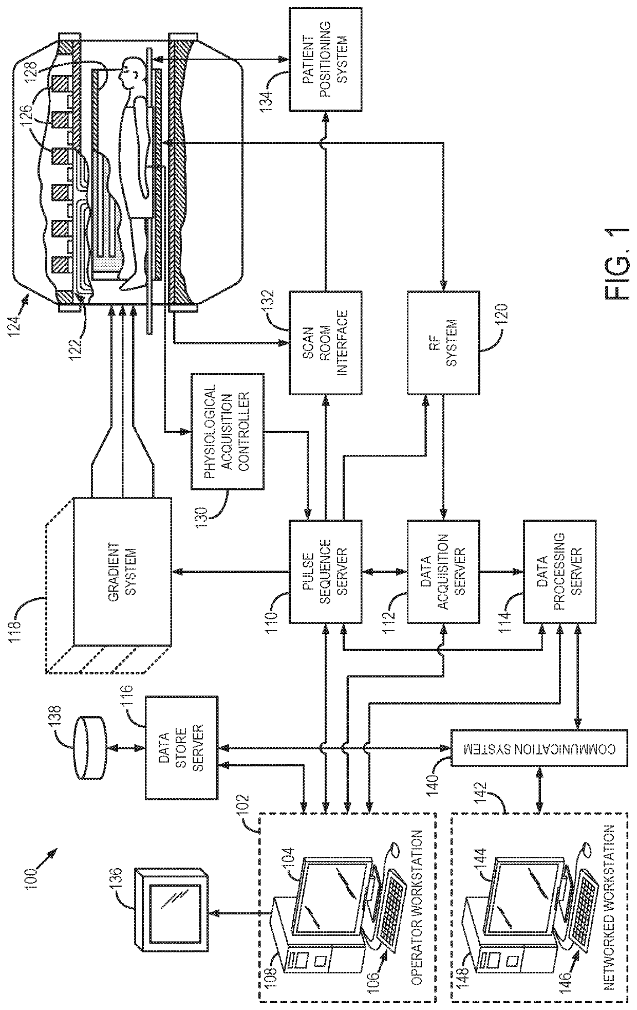
CROSS-REFERENCE TO RELATED APPLICATIONS[0001]This application represents the national stage entry of International Application PCT / US2017 / 019814, filed Feb. 28, 2017, which claims benefit of and priority to U.S. Provisional Patent Application 62 / 301,395, filed Feb. 29, 2016, which is incorporated herein by reference in its entirety for all purposes.BACKGROUND OF THE INVENTION[0002]When a substance such as human tissue is subjected to a uniform magnetic field (polarizing field B0), the individual magnetic moments of the nuclear spins in the tissue attempt to align with this polarizing field, but precess about it in random order at their characteristic Larmor frequency. Usually the nuclear spins are comprised of hydrogen atoms, but other NMR active nuclei are occasionally used. A net magnetic moment Mz is produced in the direction of the polarizing field, but the randomly oriented magnetic components in the perpendicular, or transverse, plane (x-y plane) cancel one another. If, howeve...

Claims


Application Information

Patent Timeline
Patent Type & Authority Patents(United States)
IPC IPC(8): A61B5/055G01R33/563
CPCA61B5/055G01R33/5635G01R33/56316G01R33/56325G06T2207/10088
Inventor HU, PENGWANG, DA
Owner RGT UNIV OF CALIFORNIA
Learn More