
Method for controlling an SCR catalytic converter

a technology of catalytic converter and catalytic converter, which is applied in the direction of machines/engines, engine components, mechanical equipment, etc., can solve the problems of ammonia slip, reduced ammonia storage capacity, and high level of ammonia in the first scr catalytic converter, so as to achieve the maximum efficiency of nitrogen oxide conversion and improve overall efficiency of the scr catalytic converter. , the effect of robust determination of the level

Active Publication Date: 2021-02-16
ROBERT BOSCH GMBH
View PDF6 Cites 0 Cited by
  • Summary
  • Abstract
  • Description
  • Claims
  • Application Information

AI Technical Summary

Benefits of technology

The patent describes a method for controlling an SCR catalytic converter in a vehicle engine. The method involves creating two models of the ammonia level in the converter. The second model is based on the first model, taking into account various factors such as temperature and pressure. By comparing the second model with the first model, a reliable indication of the ammonia level can be obtained. This allows for efficient control of the nitrogen oxide conversion in the converter and adjustment of ammonia slip downstream to low levels. An interpolation factor is determined to adjust the efficiency of the converter to a maximum physical efficiency, eliminating the need for a control reserve. The computer program described in the patent facilitates the implementation of the method without changing the design of the control unit.

Problems solved by technology

If the temperature of the completely full SCR catalytic converter then rises because of a load step of the combustion engine, then the ammonia storage capacity thereof decreases, which results in ammonia slip.
If too much is added, the level of ammonia in the first SCR catalytic converter is too high.
This results in excessive ammonia slip, so that a short time later the level of ammonia in the second SCR catalytic converter is also too high.
Reducing ammonia in the second SCR catalytic converter is difficult, because the first SCR catalytic converter then passes too little nitrogen oxide to decrease the level in the second SCR catalytic converter.
Ammonia slip after the second SCR catalytic converter is undesirable for environmental reasons.
Maintaining the optimum physical filling of ammonia in both SCR catalytic converters for long-term operation is impossible without an additional control strategy, even with very small tolerances.
A control reserve thus increases the system costs.
The actual level of ammonia rises far above the modelled level of ammonia and results in unexpectedly high ammonia slip.
The ammonia slip is then falsely interpreted by the software as nitrogen oxide slip, which results in a further increase in the added amount.
In this case, only complex robustness measures can avoid controller instability.

Method used


Image

  • Method for controlling an SCR catalytic converter
  • Method for controlling an SCR catalytic converter
  • Method for controlling an SCR catalytic converter

Examples


Embodiment Construction

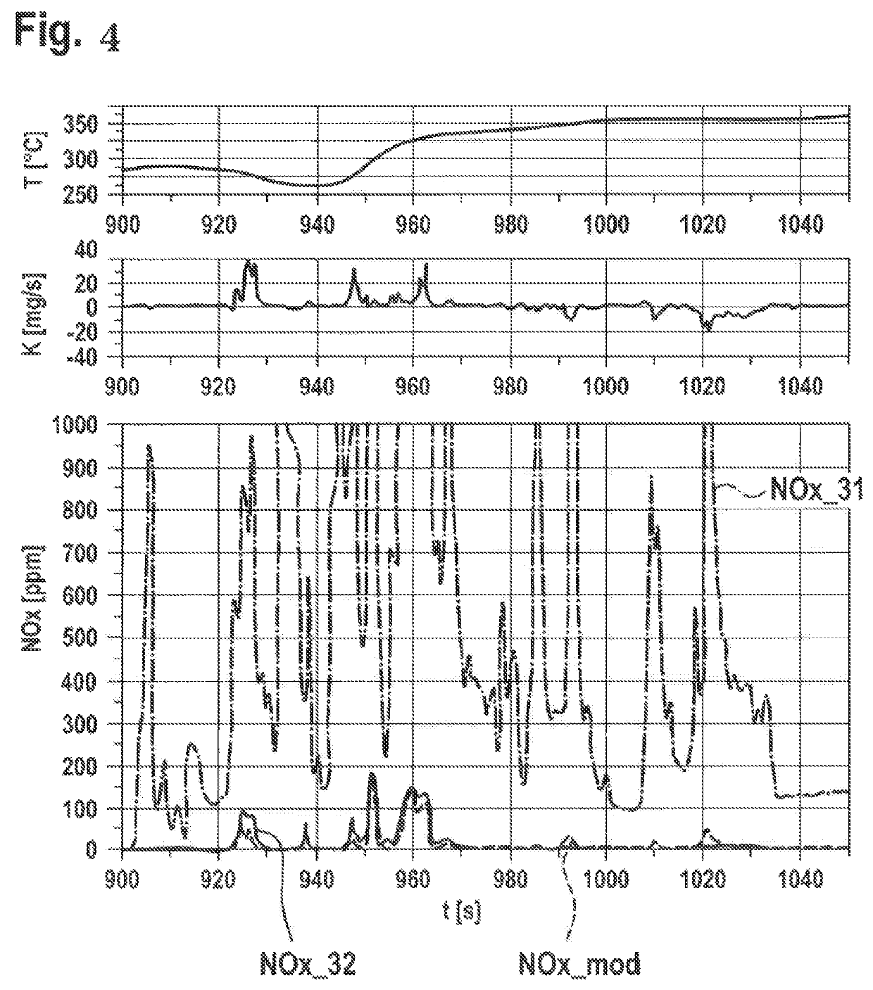
[0023]A combustion engine 10 comprises in the exhaust system 11 thereof an SCR catalytic converter system 20 that is represented in FIG. 1. Said system comprises a reducing agent metering unit 40, with which a urea-water solution can be injected into the exhaust system 11. Ammonia is released from this at the high temperatures of the exhaust gas. A first SCR catalytic converter 21 and a second SCR catalytic converter 22 are disposed downstream of the reducing agent metering unit 40. The catalytic converter material of the first SCR catalytic converter is disposed on a particle filter (SCR on filter; SCRF). A first NOx sensor 31 is disposed in the exhaust system 11 upstream of the sensor reducing agent metering unit 40. A second NOx sensor 32 is disposed between the two SCR catalytic converters 21, 22. A third NOx sensor is disposed downstream of the second SCR catalytic converter 22. All the NOx-sensors 31, 32, 33 pass the signals thereof to an electronic control unit 50.

[0024]In th...


PUM


Abstract

The invention concerns a method for controlling an SCR catalytic converter. A first modelled level of ammonia (NH3_mod1) and a second modelled level of ammonia (NH3_mod2) of the SCR catalytic converter are determined from two different models. The second modelled level of ammonia (NH3_mod2) is assessed by comparing it with the first modelled level of ammonia (NH3_mod1).

Description

BACKGROUND OF THE INVENTION[0001]The present invention concerns a method for controlling an SCR catalytic converter. Furthermore, the present invention concerns a computer program that carries out each step of the method, and a machine-readable memory medium that stores the computer program. Finally, the invention concerns an electronic control unit that is designed to carry out the method.[0002]A promising method for reducing oxides of nitrogen in oxygen-rich exhaust gases is selective catalytic reduction (SCR) by means of ammonia or ammonia-reducing reagents. The efficiency of an SCR catalytic converter is a function of the temperature thereof, of the space velocity of the exhaust gas and most decisively on the level of ammonia absorbed on the surface thereof. As absorbed ammonia is also available in addition to the directly dispensed ammonia for reduction of oxides of nitrogen, the efficiency of the SCR catalytic converter is increased compared to an empty catalytic converter. Th...

Claims


Application Information

Patent Timeline
Patent Type & Authority Patents(United States)
IPC IPC(8): F01N3/00F01N3/20F01N9/00F01N11/00
CPCF01N3/208F01N9/005F01N11/005F01N2900/0406F01N2900/0601F01N2900/1622F01N2900/1812F01N2570/14F01N2610/02Y02T10/12Y02T10/40
Inventor SCHWEIZER, FRANK
Owner ROBERT BOSCH GMBH
Learn More