
Apparatus and method for design and installation of a customizable soccer mini-pitch system

a mini-pitch and soccer technology, applied in the field of portable, prefabricated, modular and portable soccer mini-pitch systems, can solve the problems of unclear how such infrastructure (even if designed) could be transported and installed, unaddressed or under-addressed seating and lighting, and the state of the art lack of means, so as to achieve cost-effective and improve over the state of the art

Active Publication Date: 2021-02-16
MUSCO
View PDF34 Cites 2 Cited by
  • Summary
  • Abstract
  • Description
  • Claims
  • Application Information

AI Technical Summary

Benefits of technology

The patent describes a system for creating a small soccer pitch using prefabricated components that can be combined in different ways to meet different needs. These components are designed to withstand outdoor use, are modular in size, and can be easily packed and shipped. The system is cost-effective because it can be mass-produced and a large number of solutions can be created from a small number of components.

Problems solved by technology

The focus of such programs is often on play itself—giving priority to goals and playing surface when funds are limited (which they often are)—leaving such things as seating and lighting unaddressed or under-addressed.
Even if funding allows, in the current state of the art there is no well-defined approach to addressing said needs—no infrastructure which could accommodate seating and lighting and interface with goals, yet be customizable to produce each unique solution.
Additionally, many of these neighborhood spaces cannot accommodate large commercial vehicles, and so it is unclear how any such infrastructure (even if designed) could be transported and installed.
Ultimately, it is clear that value can be added to said youth development programs by adding features such as seating and lighting, but the state of the art is lacking in means to do so.

Method used


Image

  • Apparatus and method for design and installation of a customizable soccer mini-pitch system
  • Apparatus and method for design and installation of a customizable soccer mini-pitch system
  • Apparatus and method for design and installation of a customizable soccer mini-pitch system

Examples


embodiment 1

B. Exemplary Apparatus and Method Embodiment 1

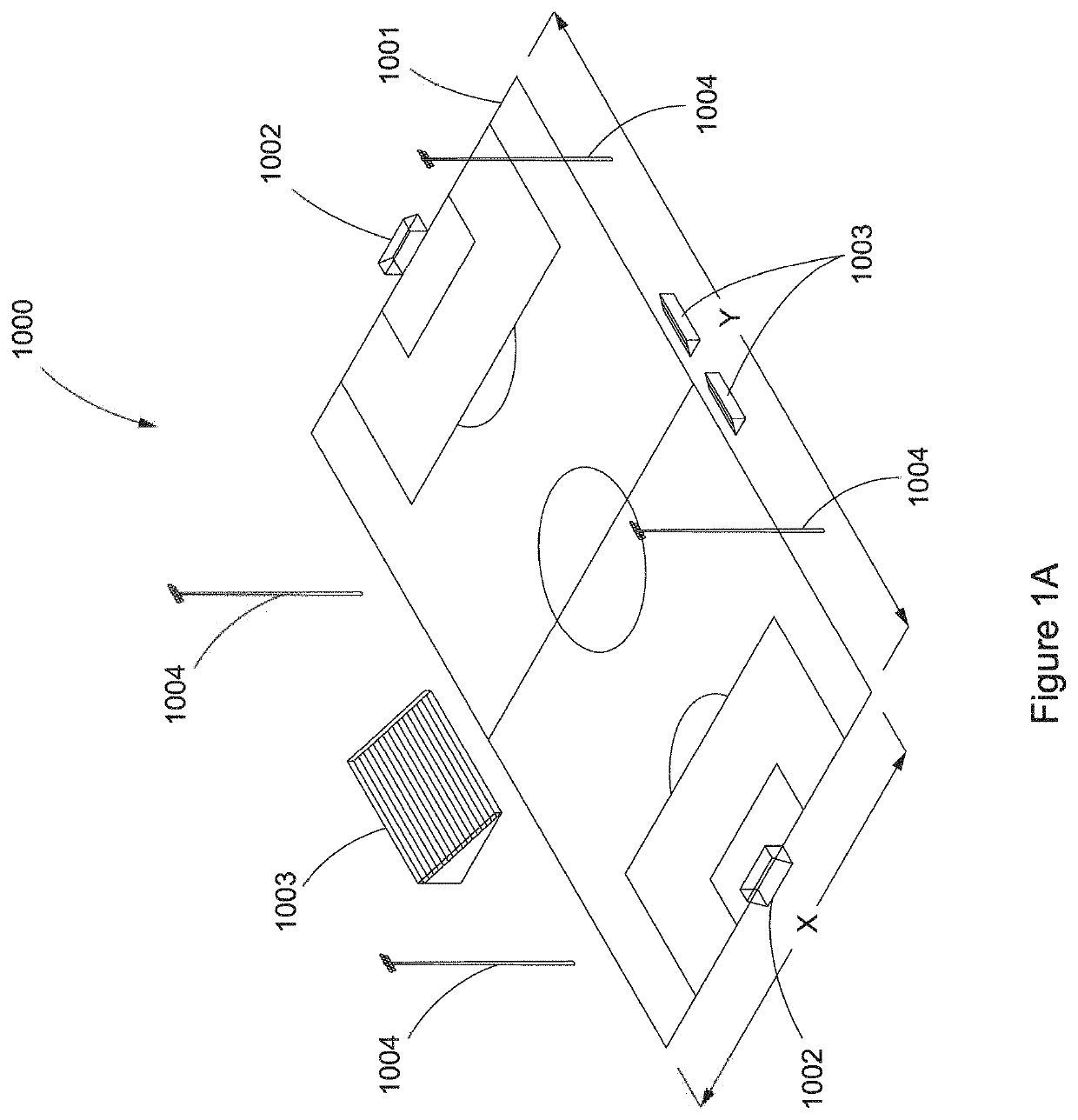
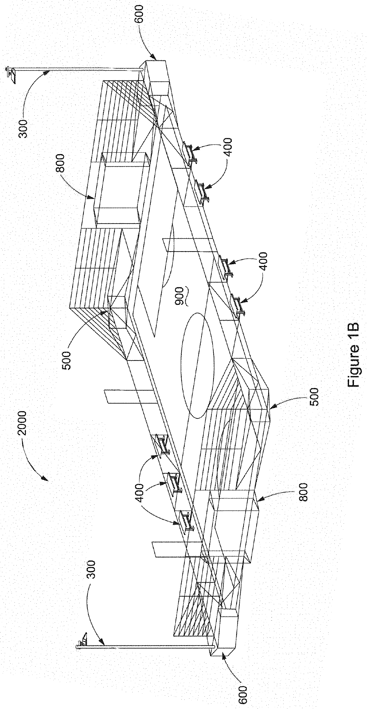
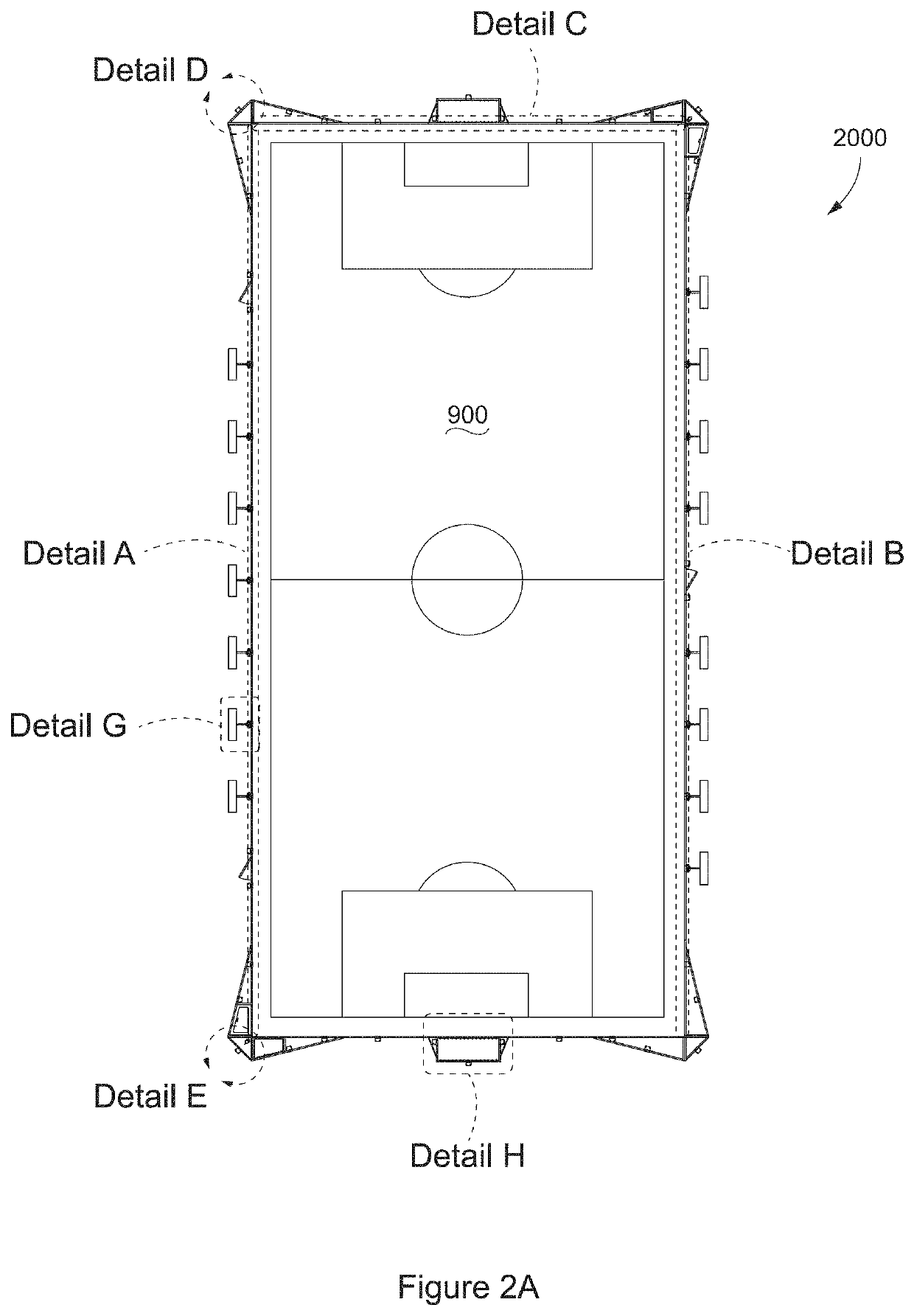
[0030]Turning to FIG. 2A—which shows a top view of a 60′×120′ field based on the generic example of FIG. 1B—one can get a sense of the components which form the system for this specific example. FIGS. 2B-I illustrate the components in greater detail, and are presently discussed.

[0031]1. Structural Components (FIGS. 2B-D)

[0032]According to the present embodiment, components are formed from 11 gauge, 2×2 A500 structural steel square tubing and / or 2″ depth, 0.120″ thick channel bar (or in some cases angle iron) so to provide rigidity, corrosion protection, impact resistance (e.g., from errant balls), and weather hardiness; said materials could be obtained from Ryerson Holding Corporation, Chicago, Ill., USA, though, of course, this could differ in material type, dimensions, and supplier. Each of components 101-107 and 201-206 is prefabricated and of a size to be transported on a standard flatbed truck (or standard shipping container); dimen...


PUM


Abstract

There exists a number of youth development programs centered on sports programming. Some of these programs operate on a platform of revitalizing neighborhood spaces to improve community engagement by creating a space for youth to enjoy sports. Oftentimes these neighborhood spaces include restrictions or the surrounding community has needs (like lighting and seating) which are unmet or under-met. Envisioned is a system approach to addressing these needs wherein a wide variety of custom solutions can be produced from prefabricated, modular, and portable components that interface with existing amenities (if any) so to enrich the youth experience and better achieve program objectives. This modular approach provides a common infrastructure for different spaces, different sports, and different levels of play.

Description

CROSS-REFERENCE TO RELATED APPLICATION[0001]This application claims priority under 35 U.S.C. § 119 to provisional application Ser. No. 62 / 703,468 filed Jul. 26, 2018, herein incorporated by reference in its entirety.I. TECHNICAL FIELD OF INVENTION[0002]The present invention generally relates to prefabricated, modular, and portable soccer mini-pitch systems customized for neighborhood spaces. More specifically, the present invention relates to providing infrastructure, seating, lighting, storage, and other features (in addition to playing surface and goals) to supplement and enrich youth development programs—such as the SOCCER FOR SUCCESS® program offered by the US Soccer Foundation—and provide greater accessibility to soccer in areas where traditional pitch development is not feasible.II. BACKGROUND OF THE INVENTION[0003]The SOCCER FOR SUCCESS® program and others like it (domestic and international) are often built on platforms of providing safe environments and physical activities ...

Claims


Application Information

Patent Timeline
Patent Type & Authority Patents(United States)
IPC IPC(8): E04H3/14A63B63/00A63G19/06E01C13/00E01C13/08
CPCE04H3/14A63B63/004E01C13/083E01C2013/006E01C13/00A63B2225/093A63B2220/807A63B2071/0625A63B2225/682A63B71/0669A63B2220/806A63B2225/687A63B71/023A63B2220/80A63B2209/00A63B71/0036A63B2225/74A63C2019/085A63C2203/10A63C19/08A63B71/02A63C19/00A63B2243/0025A63B2225/09A63B2220/89A63B2071/0694
Inventor CROOKHAM, JOE P.ROGERS, JEFFREY A.BOYLE, TIMOTHY J.HERZ, NATHAN E.
Owner MUSCO
Learn More