
Voltage detector

a voltage detector and detector technology, applied in the direction of pulse technique, process and machine control, instruments, etc., can solve the problems of gradual change of detection voltage and release voltage, degraded performance, etc., and achieve the effect of suppressing long-term degradation of performan

Active Publication Date: 2021-02-09
ABLIC INC
View PDF13 Cites 0 Cited by
  • Summary
  • Abstract
  • Description
  • Claims
  • Application Information

AI Technical Summary

Benefits of technology

[0009]The present invention provides a voltage detector capable of enhancing long-term reliability.
[0011]According to a voltage detector of the present invention, since a divided voltage is limited by an NMOS transistor receiving a constant voltage at its gate even if the voltage of a monitoring terminal greatly exceeds a release voltage, the characteristic of a transistor constituting an inversion input terminal of a comparator can be prevented from degrading, and hence long-term degradation of performance can be suppressed.

Problems solved by technology

The voltage detector therefore has a possibility that the detection voltage and the release voltage gradually change to degrade its performance in the long term.

Method used


Image

  • Voltage detector
  • Voltage detector
  • Voltage detector

Examples


Embodiment Construction

[0016]Embodiments of the present invention will hereinafter be described with reference to the accompanying drawings.

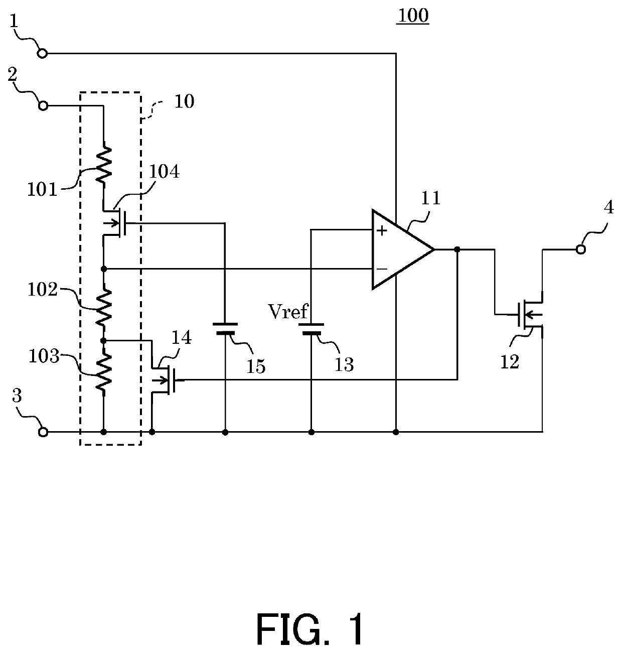
[0017]FIG. 1 is a circuit diagram illustrating an example of a voltage detector according to an embodiment of the present invention.

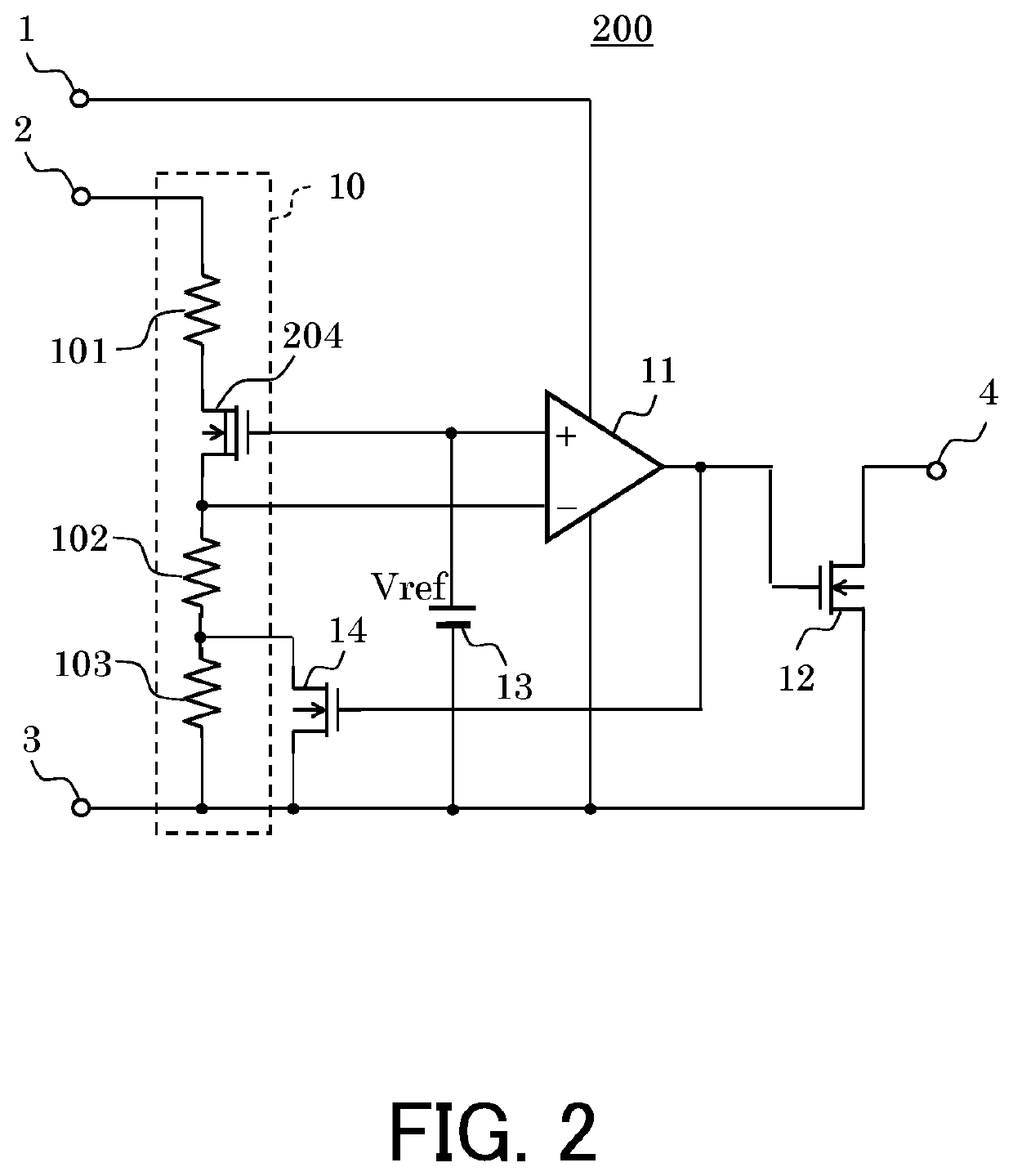
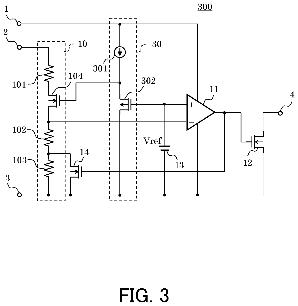
[0018]The voltage detector 100 according to the embodiment includes a voltage division circuit 10, a comparator 11, an output transistor 12, a reference voltage circuit 13, an NMOS transistor 14, and a constant voltage circuit 15. The voltage division circuit 10 has a resistor 101, an NMOS transistor 104, a resistor 102, and a resistor 103 connected in series between a monitoring terminal 2 and a ground terminal 3.

[0019]The comparator 11 has an inversion input terminal to which a source of the NMOS transistor 104 is connected, a non-inversion input terminal to which the reference voltage circuit 13 is connected, and an output terminal connected to a gate of the output transistor 12 and a gate of the NMOS transistor 14. The NMOS transistor...


PUM

PropertyMeasurementUnit
voltageaaaaaaaaaa
constant voltageaaaaaaaaaa
input voltageaaaaaaaaaa

Abstract

A voltage detector includes a voltage division circuit which outputs a divided voltage based on an input voltage, a comparison circuit which compares the divided voltage and a reference voltage to output a detection signal and a release signal, and a voltage limiting circuit which limits the divided voltage to a preset voltage.

Description

RELATED APPLICATIONS[0001]Priority is claimed on Japanese Patent Application No. 2018-100737, filed on May 25, 2018, the content of which is incorporated herein by reference.BACKGROUND OF THE INVENTION1. Field of the Invention[0002]The present invention relates to a voltage detector.2. Description of the Related Art[0003]FIG. 4 is a circuit diagram illustrating a conventional voltage detector 400 having a hysteresis.[0004]A voltage applied to a monitoring terminal 41 is divided by a voltage division circuit 42, and the divided voltage is applied to an inversion input terminal of a comparator 43. The comparator 43 provides a signal indicative of a result of comparison between the voltage to the inversion input terminal and a reference voltage which is supplied from a reference voltage circuit 44 and is applied to a non-inversion input terminal to an output terminal 47 through an NMOS transistor 45. Further, the signal of the comparator 43 is also applied to a gate of an NMOS transist...

Claims


Application Information

Patent Timeline
Patent Type & Authority Patents(United States)
IPC IPC(8): H03K5/153G01R15/04G05F1/56G01R19/165H03K5/24
CPCG01R15/04G01R19/165G05F1/56H03K5/24G01R19/16519H03K3/02337
Inventor ENDO, DAIKI
Owner ABLIC INC
Learn More