
Vibrating type hard rock cutting mechanism with function of directional high-speed abrasive jet advanced slitting

a cutting mechanism and high-speed abrasive technology, applied in cutting machines, mining structures, manufacturing tools, etc., can solve the problems of reducing reliability and working efficiency, increasing tool wear of existing equipment, and achieving efficient breaking of hard rock, so as to reduce rock breaking difficulty and improve the breaking efficiency of hard rock mass. , the effect of efficient vibration cutting and breaking of rock

Active Publication Date: 2021-01-19
CHINA UNIV OF MINING & TECH +1
View PDF9 Cites 0 Cited by
  • Summary
  • Abstract
  • Description
  • Claims
  • Application Information

AI Technical Summary

Benefits of technology

The vibrating type hard rock cutting mechanism works by using a rotating directional abrasive jet to pre-slit a contact between a disc-shaped hob and a rock, and then the disc-shaped hob vibrating and extruding the rock mass along the pre-slit, resulting in efficient vibration cutting and breaking of the rock. This mechanism reduces the difficulty and improves the efficiency of breaking hard rock, while also avoiding excessive wear on the disc-shaped hob. It is important for achieving efficient tunneling of hard rock roadways and tunnels.

Problems solved by technology

However, in the construction of hard rock mass excavation, tool wear for existing equipment is increased, and the reliability and the working efficiency are reduced.
How to achieve efficient breaking of a hard rock has become an urgent problem and puzzle to be solved.
Only increasing the power would cause the wear of a rock breaking mechanism to be intensified and the amount of working dust to be increased, thereby making it difficult to effectively improve the mechanical rock breaking efficiency, and increasing safety hazards.

Method used


Image

  • Vibrating type hard rock cutting mechanism with function of directional high-speed abrasive jet advanced slitting
  • Vibrating type hard rock cutting mechanism with function of directional high-speed abrasive jet advanced slitting
  • Vibrating type hard rock cutting mechanism with function of directional high-speed abrasive jet advanced slitting

Examples


Embodiment Construction

[0023]The present invention will be further described below with reference to the accompanying drawings.

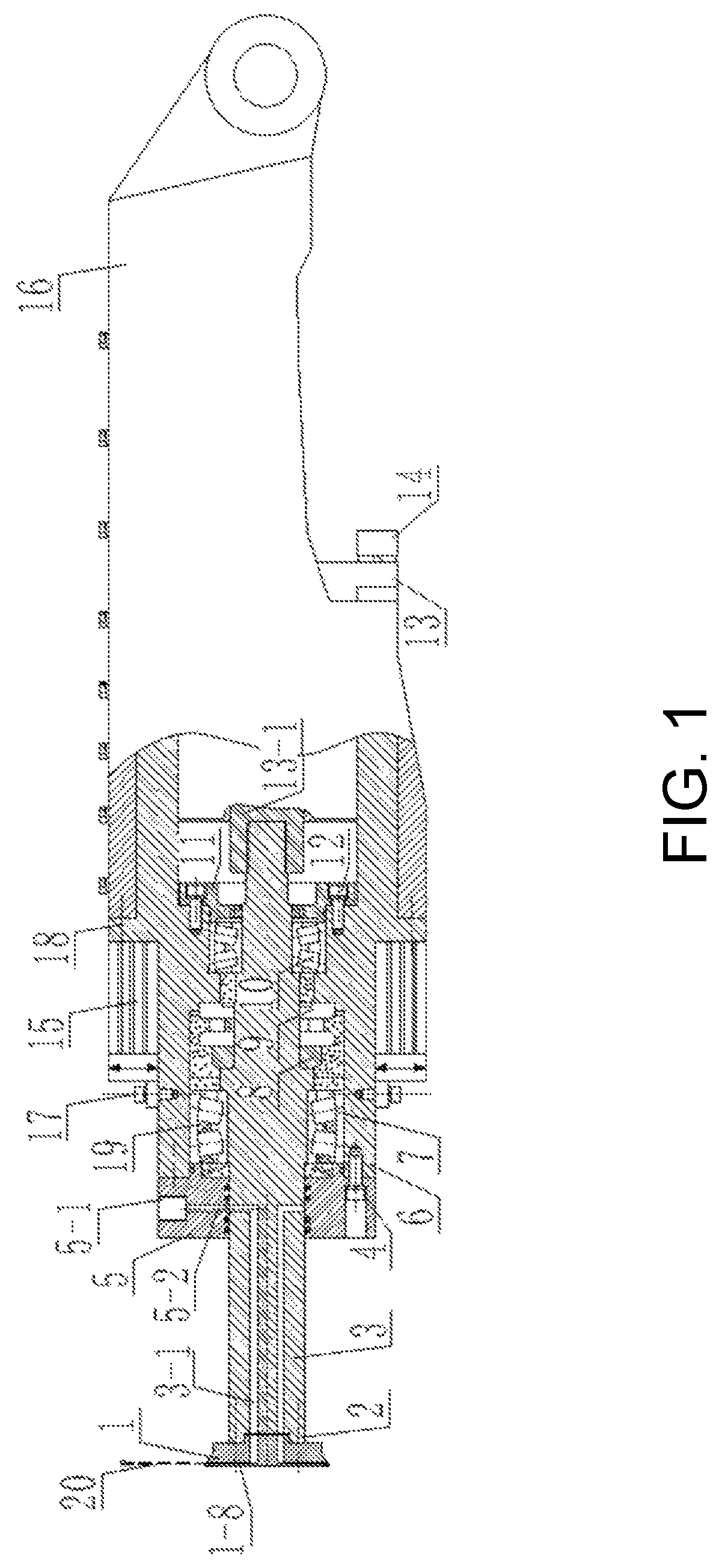
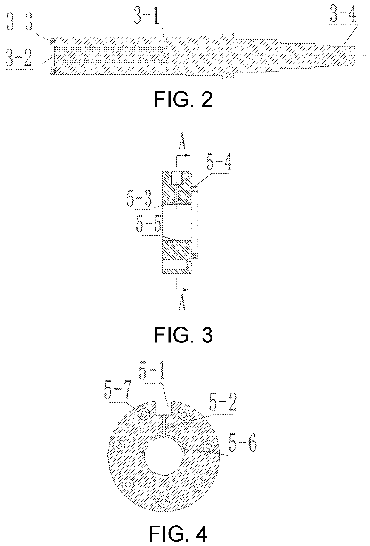
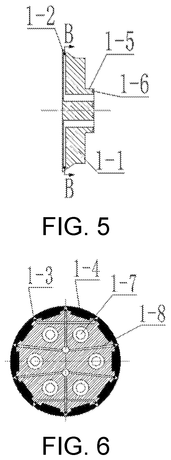
[0024]As shown in FIG. 1, a vibrating type hard rock cutting mechanism with a function of directional high-speed abrasive jet advanced slitting includes a disc-shaped hob 1, a cutting main shaft 3, a valve plate 5, a bearing end cover 11, a main shaft housing 6, a support housing 16, an axial permanent magnet motor 13, and a vibration motor 15. The main shaft housing 6 serves as a link for other components of the cutting mechanism. The axial permanent magnet motor 13, a housing and the vibration motor 15 are fixed to the main shaft housing 6 through a fourth fastening bolt 14 and a fifth fastening bolt 17, respectively. When the axial permanent magnet motor 13 works, an internal spline shaft 13-1 outputs a certain rotation speed and torque. When the vibration motor 15 works, an excitation force is output onto the main shaft housing 6.

[0025]An internal spline shaft 13-1 of the axia...


PUM

PropertyMeasurementUnit
arc angleaaaaaaaaaa
compressive strengthaaaaaaaaaa
speedaaaaaaaaaa

Abstract

A vibrating type hard rock cutting mechanism with a function of directional high-speed abrasive jet advanced slitting includes a disc-shaped hob, a cutting main shaft and a valve plate. When the vibrating type hard rock cutting mechanism works, an outlet of a high-pressure abrasive jet generating system is communicated to a cutting mechanism abrasive jet inlet. An abrasive jet enters an abrasive jet nozzle through flow channels in the valve plate, the cutting main shaft and the disc-shaped hob and forms a directional high-speed abrasive jet. The cutting main shaft is directly driven to rotate by an axial permanent magnet motor. The cutting mechanism enables the disc-shaped hob to vibrate under the action of a vibration motor. A macro crack is formed on a rock mass by rotating the abrasive jet. The rotating disc-shaped hob can be wedged into the formed crack in a vibration manner by swinging the cutting mechanism.

Description

CROSS-REFERENCE TO RELATED APPLICATION[0001]This application is a 371 of international application of PCT application Ser. No. PCT / CN2018 / 105722, filed on Sep. 14, 2018, which claims the priority benefit of China application no. 201810348455.0, filed on Apr. 18, 2018. The entirety of each of the above mentioned patent applications is hereby incorporated by reference herein and made a part of this specification.BACKGROUNDTechnical Field[0002]The present invention relates to a vibrating type hard rock cutting mechanism with a function of directional high-speed abrasive jet advanced slitting, which is suitable for tunneling hard rock roadways and tunnels.Description of Related Art[0003]Energy industry is a basic industry of the national economy and is a technology-intensive industry. “Safe, efficient and low-carbon” epitomizes the characteristics of a modern energy technology and is the main direction to seize the commanding heights of future energy technologies. The National Energy Te...

Claims


Application Information

Patent Timeline
Patent Type & Authority Patents(United States)
IPC IPC(8): E21C25/60E21D9/10E21C25/20B28D1/22
CPCE21D9/1066E21C25/20B28D1/22E21D9/1006B24C1/045B28D1/00E21D9/10
Inventor JIANG, HONGXIANGHU, ZHENGWEILIU, SONGYONG
Owner CHINA UNIV OF MINING & TECH
Learn More