
Irradiating system including a target-holder mounting in a radiation-protection enclosure and a device for deflecting an irradiation beam

a technology of irradiation system and target, which is applied in the direction of direct voltage accelerators, accelerators, electrical equipment, etc., can solve the problems of ionizing and thus dangerous for humans and the environment, heavy, bulky and expensive cells of this type of technology,

Active Publication Date: 2020-11-10
PMB
View PDF14 Cites 0 Cited by
  • Summary
  • Abstract
  • Description
  • Claims
  • Application Information

AI Technical Summary

Benefits of technology

The patent describes a system that can provide effective radiation protection while minimizing the risk of leakage. This means that the dose rate near the target holder and the particle accelerator is low, while the protection mass is reduced. The system can be installed in a single room, making it easier to access and install. Overall, the technical effect of the invention is to provide efficient and safe radiation protection in a compact design.

Problems solved by technology

These intense radiations are ionizing and thus dangerous for humans and the environment.
Depending on the materials used for the target holder, radioactive isotopes with a half-life that is short or even long (that is to say with a half-life of at least 100 days, or even a few years) may be created, which represents a drawback for this type of technology.
In order to protect persons and the surroundings from this ionizing radiation, such systems are often installed in hot cells that are heavy, bulky and expensive.
However, it is not always possible to construct a hot cell in existing installations, such as in a hospital department for example.
The development of certain applications is therefore hindered by constraints associated with the possibilities of installing these irradiation systems.
It follows that such a radiation protection chamber does not therefore prevent the radiation coming from the target from significantly activating the particle accelerator and that the mass of the radiation protection remains high (typically 40 to 80 metric tons for cyclotrons producing protons of 10 to 18 MeV, to which 10 to 20 metric tons are to be added for the particle accelerator itself).
These solutions thus make it possible to reduce the risks associated with the non-remnant radiation but do not protect the accelerator from activation by the radiation coming from the target and, on account of their mass, do not facilitate the installation of the accelerators, or are sometimes even prohibitive for an installation in pre-existing buildings.
This is particularly a hindrance for neutron that “rebound” against the metal surfaces of the accelerator by elastic impact.
If the installation constraints cause the construction of thick walls to be avoided, this sending back of neutrons is all the more a hindrance in that it generates a high dose rate by itself.
The use of an offset target thus makes it possible to greatly reduce the radiation protection mass, but risks of irradiating the surroundings linked to such neutron leakage remain.
However such a solution generally requires destroying a pre-existing vacuum in the system, changing the target then re-establishing the vacuum before being able to re-use the system.
Such a solution does not therefore enable the problem of neutrons coming back towards the particle accelerator.

Method used


Image

  • Irradiating system including a target-holder mounting in a radiation-protection enclosure and a device for deflecting an irradiation beam
  • Irradiating system including a target-holder mounting in a radiation-protection enclosure and a device for deflecting an irradiation beam

Examples


Embodiment Construction

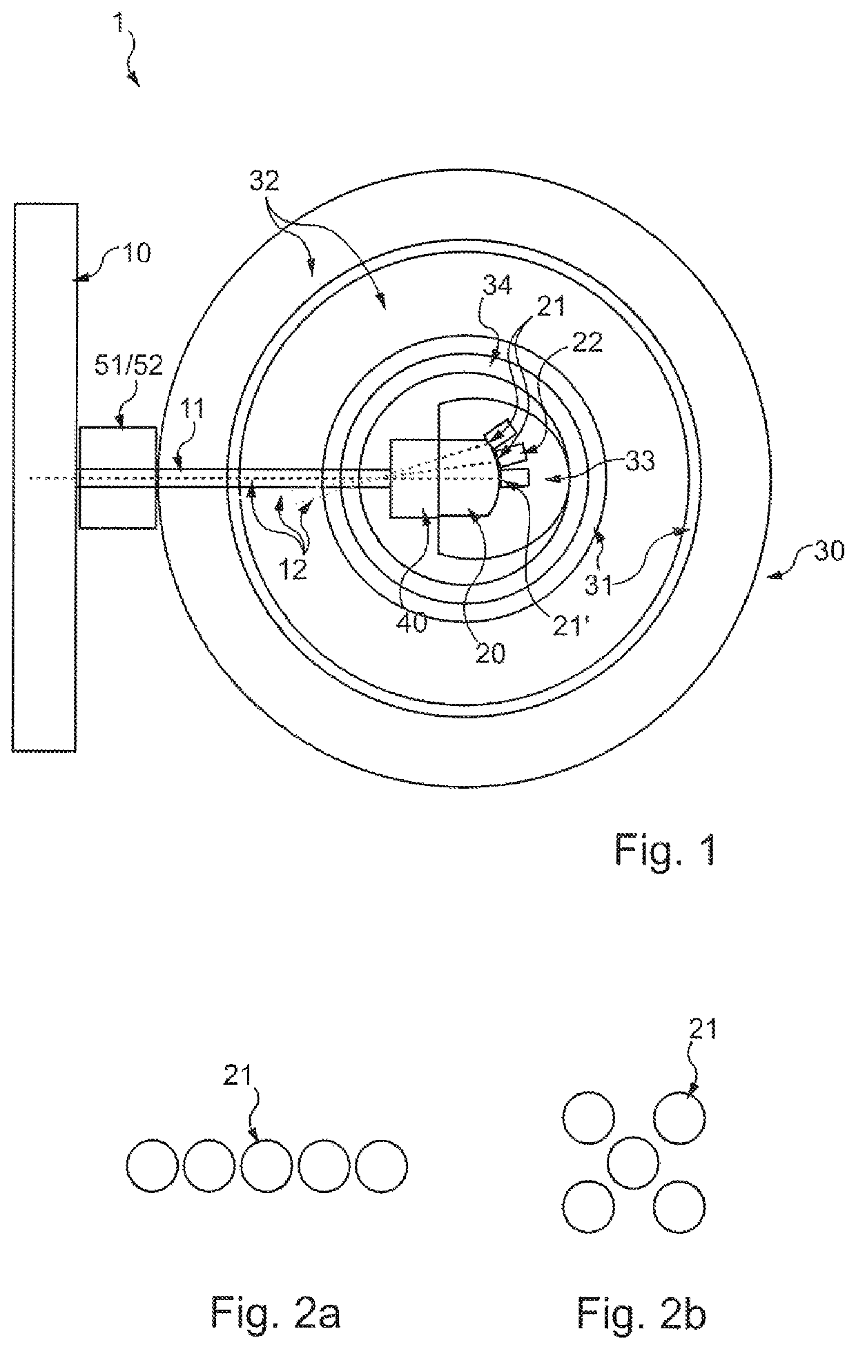
[0110]Identical parts represented in the aforementioned figures are identified by identical numerical references.

[0111]FIG. 1 presents an irradiation system 1 comprising a particle accelerator 10, a target holder mounting 20 and a radiation protection chamber 30.

[0112]The particle accelerator 10 is for example a cyclotron. It is for example configured to emit an irradiation beam 11 comprising a beam of protons of several megaelectrons (MeV).

[0113]The radiation protection chamber 30 here surrounds the target holder mounting 20. The particle accelerator 10 is positioned outside the chamber 30.

[0114]The radiation protection chamber 30 for example takes the form of a hollow sphere, comprising a wall formed by stacking successive layers.

[0115]For example, the wall of the radiation protection chamber 30 comprises an alternating arrangement of a layer of a so-called “dense” material 31 and of a layer hydrogen-rich material 32.

[0116]In practice, it is preferable for the radiation protection...


PUM


Abstract

Disclosed is a system for irradiating a target. The system includes a particle accelerator configured to at least emit an irradiation beam along an axis, a target-holder mounting outside the accelerator, a radiation-protection enclosure surrounding the target-holder mounting, and a deflection device. The particle accelerator is positioned outside the enclosure. The target-holder mounting includes at least one port configured to receive a target holder for a target to be irradiated. The target-holder mounting is stationary relative to the particle accelerator. The port is offset relative to the axis of the irradiation beam. The deflection device is positioned in the radiation-protection enclosure and is configured to divert the irradiation beam towards the port of the target holder in which the target to be irradiated is inserted.

Description

BACKGROUND OF THE INVENTIONField of the Invention[0001]The present application concerns a target irradiation system, and in particular an irradiation system comprising a particle accelerator.Description of the Related Art[0002]Particle accelerators are pieces of equipment the object of which is to produce beams characterized firstly by the nature of the particles (protons, electrons, etc.), the energy of the particles and the beam current. According to the application for which the accelerator is used (production of radio-isotopes, radiotherapy by x-rays or gamma rays, production of neutrons, etc.) the beam may interact with different types of target, for example principally:[0003]Targets in the core of which nuclear reactions take place, for example such as the targets used with cyclotrons for the production of radioisotopes for Positron Emission Tomography (PET);[0004]Stopping block targets the object of which is to stop and characterize the beam at the time of the adjustment phas...

Claims


Application Information

Patent Timeline
IPC IPC(8): G21K5/08H05H6/00G21G1/10G21K1/093
CPCG21K5/08H05H6/00G21K1/093G21G1/10H05H2006/007
Inventor MASSE, NICOLASTANNOURY, NANCYPEREZ DELAUME, ALAIN
Owner PMB
Learn More