
Bonding objects together

a technology of objects and bonding elements, applied in the field of mechanical engineering and construction, can solve the problems of new challenges in bonding elements of these materials, substantial galvanic corrosion, and special difficulties, and achieve the effects of strong heating, high energy absorption, and potentially very fast processing

Active Publication Date: 2020-10-20
WOODWELDING
View PDF10 Cites 0 Cited by
  • Summary
  • Abstract
  • Description
  • Claims
  • Application Information

AI Technical Summary

Benefits of technology

The present invention provides an effective and low-cost method of bonding a connector to an object or joining two objects together using a connector. The method involves using energy directors, which are shaped to concentrate vibration energy to a small area where liquefaction occurs. This results in stronger heating and enhanced internal friction, leading to improved bonding.

Problems solved by technology

The new materials cause new challenges in bonding elements of these materials—especially of bonding flattish objects (such as panels or boards) together or bonding a flattish object and an other object together, such as bonding a flattish object to an other object, or bonding a connector to a flattish object.
Difficulties especially arise if objects of different materials are to be connected, such as two materials of the group including steel, aluminium, magnesium, fiber composites, especially carbon fiber composites or glass fiber composites—together.
Conventional rivet connections with metallic rivets firstly suffer from the drawback that the electrochemical potential of some of these materials is strongly different with differences corresponding to several volts, so that there will be substantial galvanic corrosion.
Rivets from stainless steel that partially solve the problem are firstly expensive, and secondly only austenitic stainless steel can be used, which material has a limited hardness and strength.
Also, connections involving flat parts of fiber reinforced polymers suffer from the additional drawback that the out-of-plane Young's modulus of these materials is very low, and the friction force arising from the compression of the parts between the rivet head and rivet foot does not substantially contribute to the mechanical stability of the connection.
However, lacquer may become brittle over time, especially when subject to long-time mechanical wear due to vibration, or it can dissolve.
Adhesive bonds can be light and strong but suffer from the disadvantage that there is no possibility to long-term control the reliability, since a degrading adhesive bond, for example due to an embrittling adhesive, is almost impossible to detect without entirely releasing the bond.
As a further limitation of manufacturing processes for example in the automotive industry, the adhesives of choice do not bond immediately after their deposition.
However, during this step, substantial forces act on the parts.

Method used


Image

  • Bonding objects together
  • Bonding objects together
  • Bonding objects together

Examples


Embodiment Construction

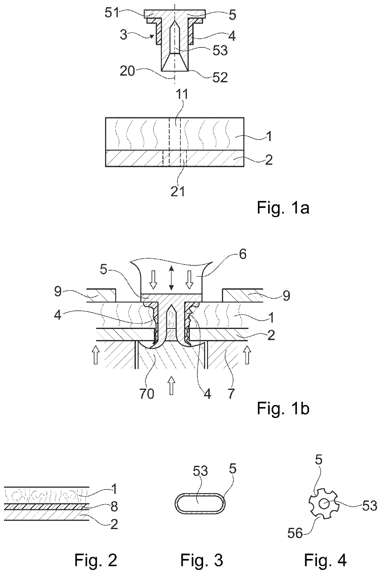
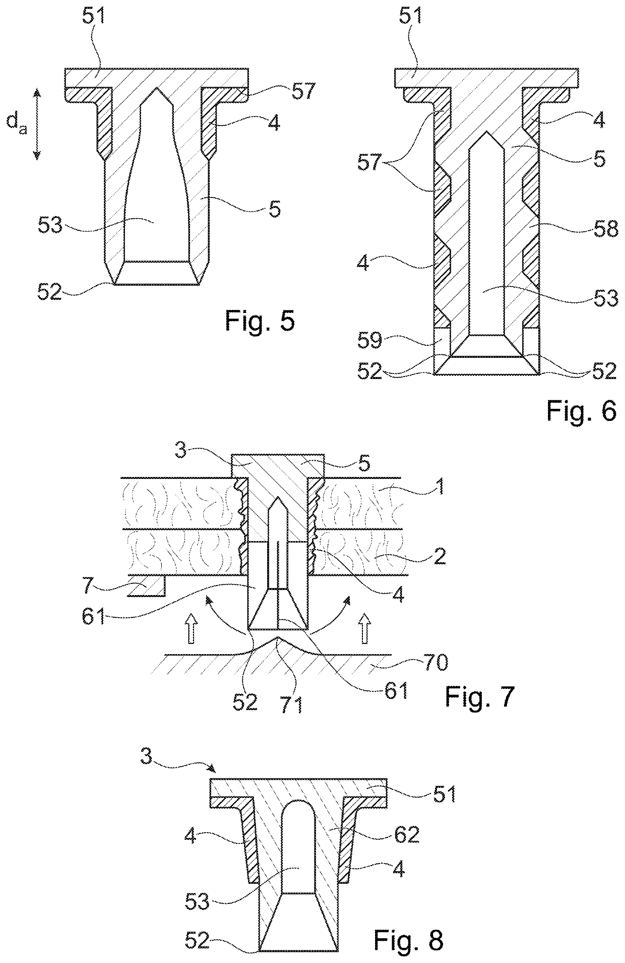
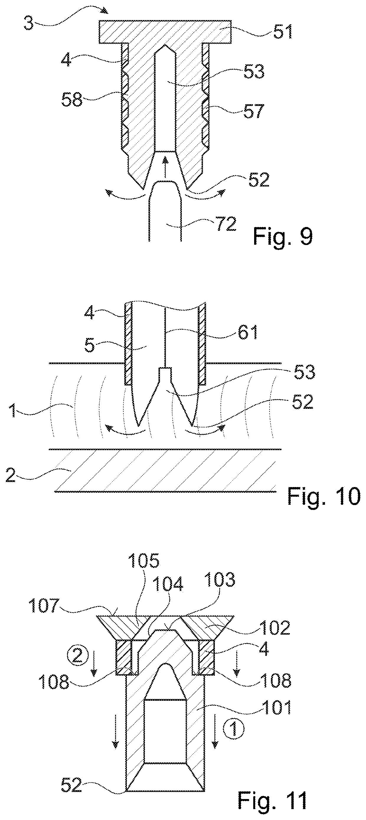
[0138]FIG. 1a depicts a basic set-up of embodiments of the invention. The first object 1 is a board or sheet, for example of a fiber composite material (fiber reinforced polymer material) such as a Carbon fiber-reinforced polymer (CFRP) or a Fiberglass. It has an essentially flat sheet portion with two, for example, essentially parallel broad surfaces. The broad surface that in the figures is the upper surface is herein termed “proximal” surface and the opposing surface is the “distal” surface.

[0139]The second object 2 is made of a metal. It also has a sheet portion with the proximal broad surface of the sheet portion lying against the distal broad surface of the first object's sheet portion.

[0140]In a variant shown in FIG. 2, between the first and second objects a further layer, such as an adhesive and / or separating insulating layer 8, may be present. Such additional layer may, for example, be formed of a thermoplastic material, or it may be formed of a resin, for example a not cur...


PUM

PropertyMeasurementUnit
glass transition temperatureaaaaaaaaaa
sizeaaaaaaaaaa
temperatureaaaaaaaaaa

Abstract

A method of bonding a connector to a first object includes providing the first object and the connector, the connector extending between a proximal end and a distal end and has a connector body that forms a distally facing punching edge. At least one of the connector and of the first object includes a thermoplastic material in a solid state. The method further includes driving the connector into the first object and coupling mechanical vibration into the connector until the connector extends through a portion of the first object from a proximal side to a distal side thereof and material of the first object is punched out by the connector body, and until at least a flow portion of the thermoplastic material becomes flowable and flows relative to the first object and the connector body while the connector body remains solid. Thereafter, the thermoplastic material is allowed to re-solidify.

Description

BACKGROUND OF THE INVENTIONField of the Invention[0001]The invention is in the fields of mechanical engineering and construction, especially mechanical construction, for example automotive engineering, aircraft construction, shipbuilding, machine construction, toy construction etc.Description of Related Art[0002]In the automotive, aviation and other industries, there has been a tendency to move away from steel constructions and to use lightweight material such as aluminium or magnesium metal sheets or die-cast parts, or carbon fiber reinforced polymers instead.[0003]The new materials cause new challenges in bonding elements of these materials—especially of bonding flattish objects (such as panels or boards) together or bonding a flattish object and an other object together, such as bonding a flattish object to an other object, or bonding a connector to a flattish object.[0004]Difficulties especially arise if objects of different materials are to be connected, such as two materials o...

Claims


Application Information

Patent Timeline
Patent Type & Authority Patents(United States)
IPC IPC(8): B23B7/00B21J15/28F16B5/04B29C65/64B21J15/02B21J15/08B21J15/36B21J15/14B29C65/56B29C65/00F16B19/08F16B11/00
CPCF16B5/04B21J15/08B21J15/147F16B19/086B29C66/742B21J15/025B29C65/645B29C65/562B21J15/285B21J15/36B29C66/8322F16B11/006B29C66/41B29C66/92921B29C66/721B29C66/21B29C66/81423B29C66/92445B29C66/81429B29C66/1122B29C66/727B29C66/83221B29C66/92443B29C66/7212B29K2307/04B29K2309/08B21J15/12
Inventor MAYER, JÖRGLEHMANN, MARIOKVIST, JOAKIMPOSCHNER, PATRICIA
Owner WOODWELDING
Learn More