Apparatus and method for establishing quantum oscillations

a quantum oscillation and apparatus technology, applied in the field of apparatus and method for establishing quantum oscillations, can solve the problems of inability to achieve a spin-photon coupling rate greater than 1 hz, inability to achieve the upper limit of the spin-cavity excitation transference anyway, and the weak electromagnetic field of the cavity mode to allow efficient coherentness

Active Publication Date: 2020-08-04
IMPERIAL COLLEGE OF SCI TECH & MEDICINE +1
View PDF5 Cites 1 Cited by
  • Summary
  • Abstract
  • Description
  • Claims
  • Application Information

AI Technical Summary

Benefits of technology

[0013]By having a sufficiently high concentration of said species of the gain medium, and optical pumping the resonator structure using one or more short pulses of nanosecond duration, or a burst of approximately a millisecond in duration at relatively low instantaneous optical power, this enables the coherence of the spin-ensemble to be preserved, thereby enabling quantum oscillations to be exhibited at room temperature.

Problems solved by technology

However, the individual coupling of magnetic spins to the electromagnetic field of a cavity mode is too weak to allow for efficient coherent transfer of excitation (information) to and from the spins on a timescale shorter than the spin decoherence and cavity decay times. This requires the spin-cavity system to be in the “strong coupling” regime, where the coupling rate exceeds both the spin decoherence and cavity decay rates.
It can be increased by reducing the mode volume (physical size of the resonator), but practically it is difficult to achieve a spin-photon coupling rate greater than 1 Hz.
This upper limit is anyway impractical for spin-cavity excitation transference considering that spin coherence times are usually of the order of 10-1000 μs even at low temperatures.
However, this approach still relies on cryogenic temperatures in order to preferentially populate and thus polarize the spin sub-levels.
It will be appreciated that the use of cryogenic temperatures significantly increases the complexity, usability and cost of practical systems for establishing coherent quantum oscillations, in turn hindering the development of quantum information processing systems.

Method used


Image

  • Apparatus and method for establishing quantum oscillations
  • Apparatus and method for establishing quantum oscillations
  • Apparatus and method for establishing quantum oscillations

Examples


examples

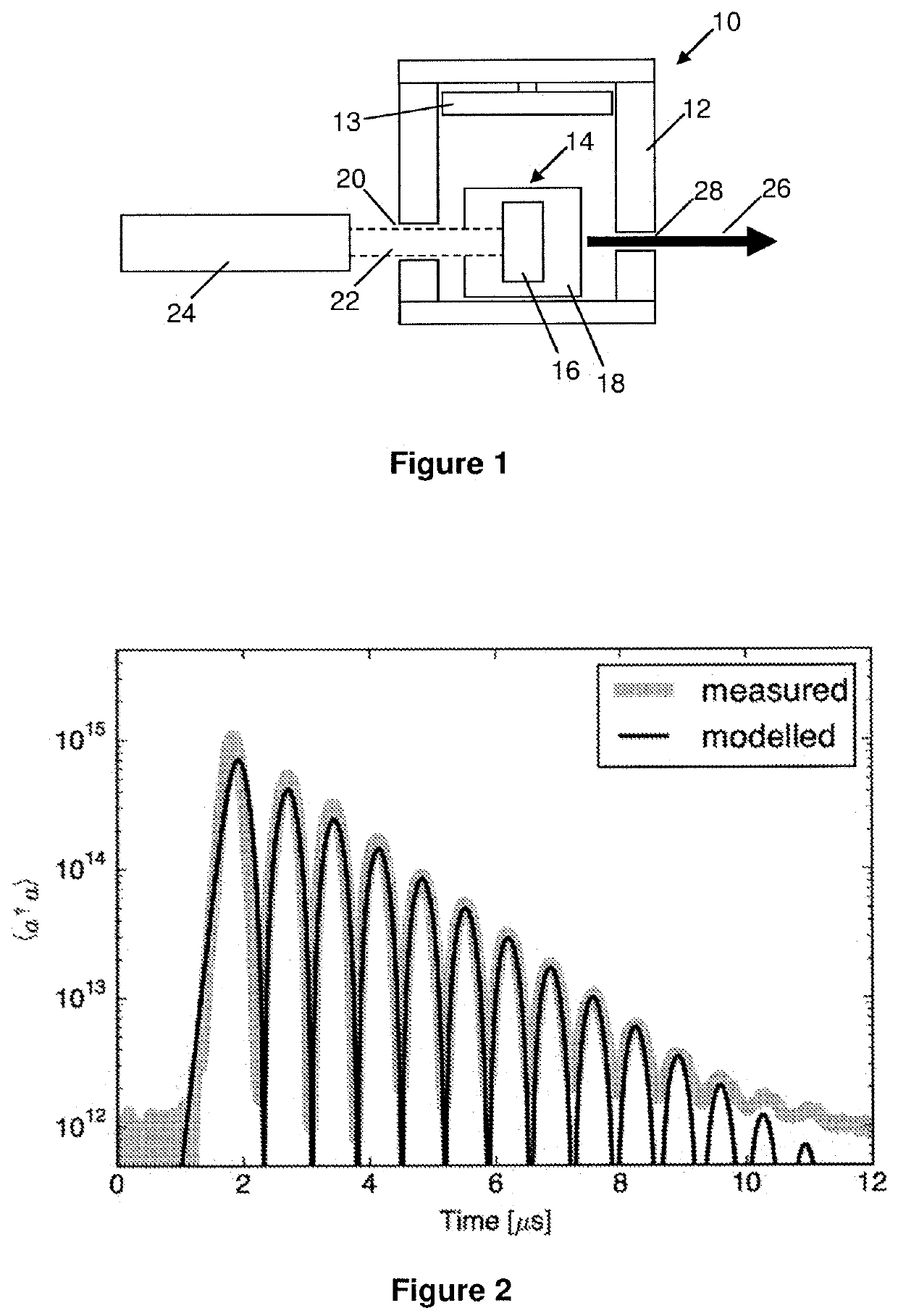
[0081]As mentioned above, a working room-temperature device has been demonstrated and its performance characterised. In more detail, this device is based on a strontium titanate (STO) dielectric resonator containing a single crystal of p-terphenyl highly doped with pentacene. The resonant frequency of the cavity matches the X-Z transition of the pentacene at 1.45 GHz and has a quality factor (Q) of around 10,000. The spin decoherence time of the pentacene is approximately 10 μs, which is roughly the same as the cavity mode lifetime (˜7 μs). The pentacene-doped medium was excited by a ˜4 ns optical pulse (600 nm) and produced a Rabi oscillation frequency of ˜2 MHz and period of about 0.5 μs. This corresponds to a spin-photon coupling rate of 1 MHz. The Rabi oscillation frequency is due to the spin-ensemble and cavity mode populations ‘splitting’. A number of oscillations (at least 10) in the cavity mode population were observed (see FIG. 2) during the lifetime of the phenomenon.

[0082...


PUM


Abstract

Apparatus and method establish quantum oscillations at room temperature. A cavity has therein a resonator structure that includes a resonant element and a gain medium. A species of the gain medium has an electronic spin multiplicity capable of supporting a two-level spin system. An optical pump pumps the resonator structure and thereby generates microwave output power through stimulated emission of thermal photons. The species of the gain medium is of a sufficiently high concentration such as to have an ensemble spin-photon coupling rate which exceeds both the cavity mode decay rate and the spin-spin decoherence rate. The optical pump pumps the resonator structure using a short pulse of nanosecond duration, or a burst of approximately a millisecond in duration at relatively low instantaneous optical power, to excite said species of the gain medium into a spin-polarized two-level system that exhibits quantum oscillations in the microwave output power.

Description

FIELD OF THE INVENTION[0001]The present invention relates to an apparatus and method for establishing quantum oscillations between spin-ensembles and a cavity, with the ability to achieve such quantum oscillations at room temperature.BACKGROUND TO THE INVENTION[0002]The resonant coupling of atoms or spins (electronic or nuclear) to cavity modes has been a mainstay area of research in the field of quantum optics for many decades, and has recently attracted renewed interest in the field of quantum information processing and quantum computing where the spins serve as a quantum memory (qubits). However, the individual coupling of magnetic spins to the electromagnetic field of a cavity mode is too weak to allow for efficient coherent transfer of excitation (information) to and from the spins on a timescale shorter than the spin decoherence and cavity decay times. This requires the spin-cavity system to be in the “strong coupling” regime, where the coupling rate exceeds both the spin deco...

Claims


Application Information

Patent Timeline
Patent Type & Authority Patents(United States)
IPC IPC(8): H01S1/02G06N10/00B82Y10/00
CPCB82Y10/00H01S1/02G06N10/00
Inventor BREEZE, JONATHAN DAVID BAXENDALESALVADORI, ENRICOKAY, CHRIS
Owner IMPERIAL COLLEGE OF SCI TECH & MEDICINE
Why Eureka
Try Eureka