
HVAC system of the vehicle passenger compartment with air flow topology alteration

a technology of air flow and passenger compartment, which is applied in the direction of vehicle heating/cooling devices, compression machines with several evaporators, light and heating apparatus, etc., to achieve the effect of improving system efficiency and improving system efficiency

Active Publication Date: 2020-06-30
PRIVREDNO DRUSTVO ZA PRUZANJE USLUGA IZ OBLASTI AUTOMATIKE I PROGRAMIRANJA SYNCHROTEK D O O
View PDF19 Cites 1 Cited by
  • Summary
  • Abstract
  • Description
  • Claims
  • Application Information

AI Technical Summary

Benefits of technology

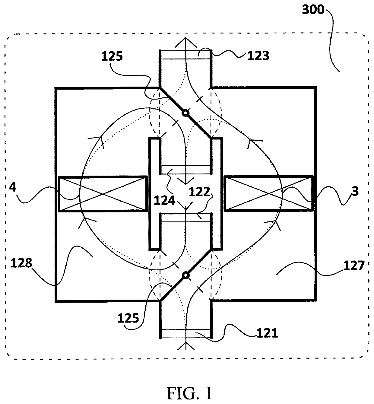
The HVAC system for the passenger compartment of this patent ensures that the air flows are always separated, regardless of external temperature or internal air flows. This separation enables the system to operate in different modes without the need for switching between them. A simple control system is used, with only two states for the air flow sub-system, which helps to improve system efficiency. In the cooling mode, the external air flow is directed over the internal heat exchanger to cool the air stream, while in the heating mode, the air stream is directed over the internal heat exchanger and the additional heating device to heat the passenger compartment. The HVAC system also allows for the recovery of heat from the air leaving the passenger compartment, while preventing freezing of the condensed water from the air stream.

Problems solved by technology

The mentioned disadvantages of the HVAC system in which the alteration of the working mode is achieved by changing the topology of the refrigerant flow, as well as the disadvantages of the HVAC system in which this alteration is achieved by changing the mass ratios of warm and cool air streams are eliminated by the proposed system, in which the alteration in the working mode is achieved by changing the topology of the internal and external air flows.

Method used


Image

  • HVAC system of the vehicle passenger compartment with air flow topology alteration
  • HVAC system of the vehicle passenger compartment with air flow topology alteration
  • HVAC system of the vehicle passenger compartment with air flow topology alteration

Examples


second embodiment

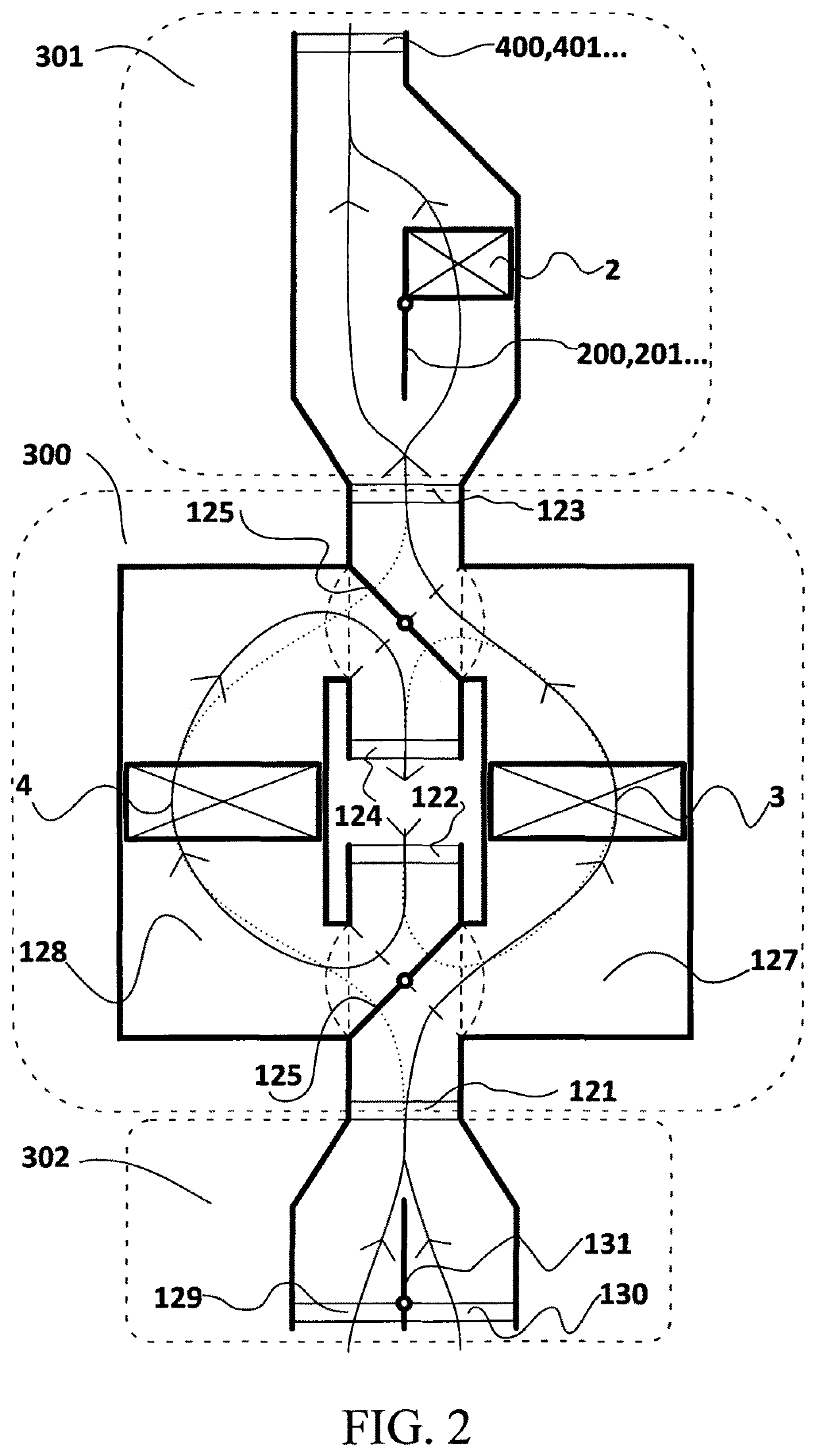
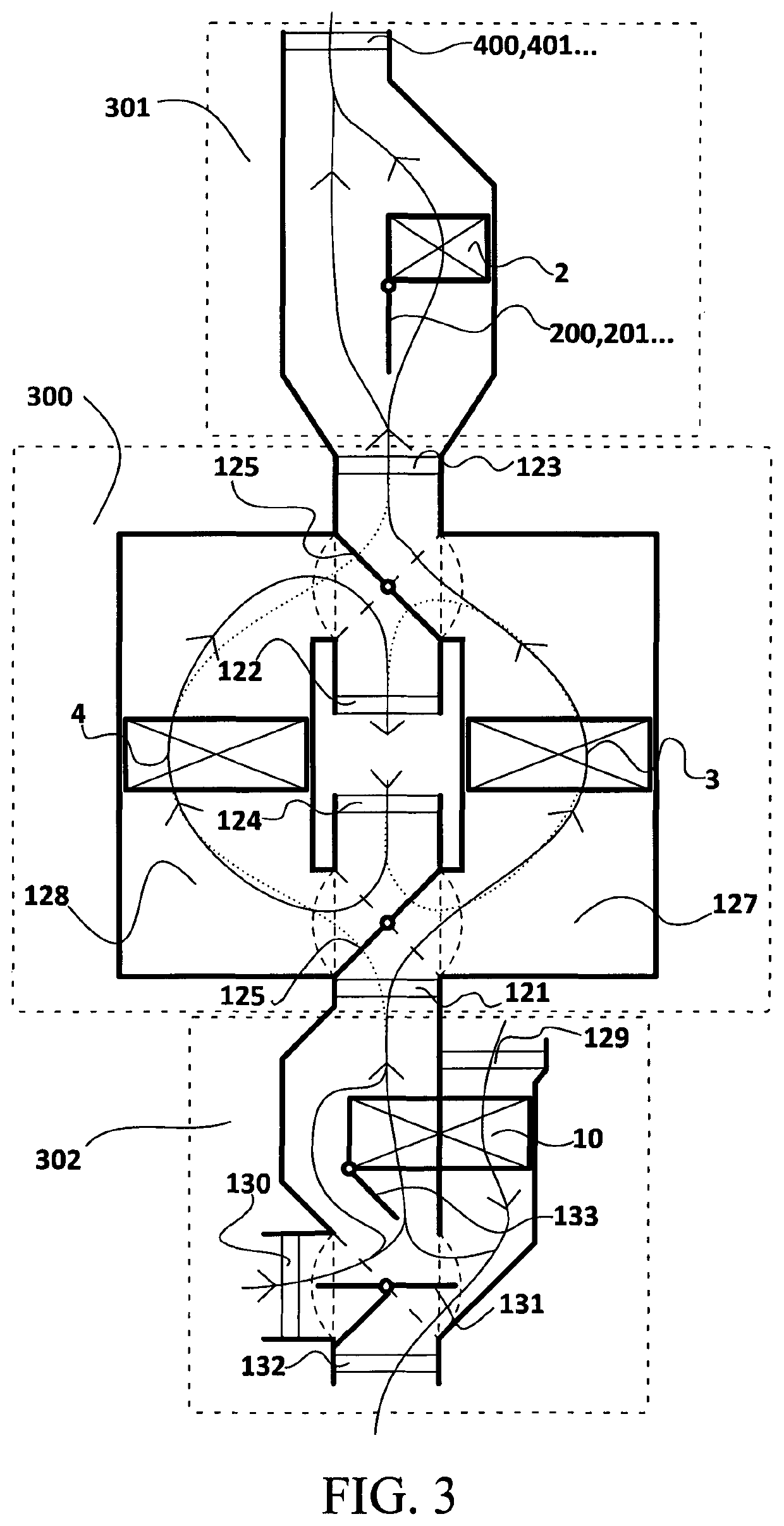
[0071]FIG. 2 presents the said invention, which additionally includes a device 301 for additional heating connected with the subsystem 300 for altering air flow topology via the outlet 123 of the internal air stream and a subsystem 302 for air quality which is connected with the subsystem 300 for altering air flow topology which is connected with the system 300 for altering air flow topology via the inlet 121 of the internal air flow.

[0072]The device 301 for additional heating includes a heat exchanger 2 for heating, and temperature regulation flaps 200, 201, . . . 20n. The internal air flow is divided into a plurality of zone air flows, one for each conditioning zone. The air stream of an air flow zone is by a corresponding temperature regulation flap 20x (where x=0, 1, 2 etc. n) divided into two air streams, of which the first air stream is heated on the heat exchanger 2 for heating, while the other bypasses the heat exchanger 2 for heating, and then the mixture of these two air s...

fifth embodiment

[0076]FIG. 5 presents the said invention. The compressor 1 compresses and propels the refrigerant which flows through the heat exchanger 2 for heating, the first adjustable throttle valve 5 which relieves the pressure of the refrigerant, the medium pressure heat exchanger 3, and the second adjustable throttle valve 6 which reduces the flow of the refrigerant through the evaporator 4. This forms a refrigerant cycle with permanent topology of the refrigerant flow, which connects the heat exchanger 2 for heating, the medium pressure heat exchanger 3 and evaporator 4.

[0077]When the flaps 125 for altering the air flow topology is placed in the position in which the air chamber of the medium pressure exchanger 127 is included in the internal air flow, the air stream of the internal air flow is cooled, dehumidified or heated on the medium pressure heat exchanger 3, in order to be additionally heated in the additional heating device 301, where it receives the heat from the heat exchanger 2 ...

sixth embodiment

[0079]FIG. 6 presents the said invention. The refrigerant cycle additionally includes a heat exchanger for collecting waste heat from electrical or mechanical assemblies 7, with associated first additional throttle valve 8. Accordingly, collection of waste heat is enabled in the refrigerant cycle from electrical or mechanical assemblies, and their cooling, without introducing additional switching valves. Cooling the assemblies is achieved independently of the working mode of the HVAC system.


PUM


Abstract

The HVAC system of a vehicle passenger compartment with air flow alteration, which pertains to the system of air conditioning with several working modes for air conditioning of the passenger compartment, i.e. to the system that allows for cooling, heating, and dehumidifying of the space inside the vehicle passenger compartment, according to the present invention, comprises a refrigerant cycle which includes a compressor (1), heat exchanger (2) for heating, the first adjustable throttle valve (5), medium pressure heat exchanger (3), the second adjustable throttle valve (6), and an evaporator (4); and that comprises a subsystem (300) for altering the air flow topology inside which are placed the medium pressure heat exchanger (3) and the evaporator (4), a device (301) for additional heating inside which is placed the heat exchanger (2) for heating, external air flow which leads the air through the subsystem (300) for altering the topology of air flow into the environment, and the internal air flow that leads the air through the subsystem (300) for altering the air flow topology and the device (301) for additional heating into the passenger compartment; while the subsystem (300) for altering the air flow topology has at least two working modes, so that in the first working mode the external air flow includes the medium pressure heat exchanger (3), and the internal air flow includes the evaporator (4), whereas in the second working mode the external air flow includes the evaporator (4), and the internal air flow includes the medium pressure heat exchanger (3); and where the said system (300) realises at least one of the functions of heating, cooling, and dehumidifying of the passenger compartment air.

Description

TECHNICAL FIELD[0001]The HVAC system of the vehicle passenger compartment with air flow topology alteration pertains to a system of air-conditioning with several working modes of air-conditioning of the passenger compartment, i.e. to a system that provides cooling, heating, and dehumidifying of the space within the passenger compartment, and belongs to devices for circulation of cooling means that use ducts, as well as the layout or installment of heating, cooling, or airing / refreshing devices in vehicle passenger compartments. Int. Cl8.: B 60H 1 / 00 (2015.01); F 25B 29 / 00 (2015.01); F 25D 17 / 08 (2015.01)TECHNOLOGY PROBLEM[0002]The HVAC system of the vehicle passenger compartment with air flow topology alteration according to the invention is aimed at providing a novel HVAC system with a novel structure and layout of the system elements, which will simplify the system assembly so that it will not include any switching valves for topology alteration of the flow of the refrigerant, imp...

Claims


Application Information

Patent Timeline
Patent Type & Authority Patents(United States)
IPC IPC(8): B60H1/00B60H1/32B60H1/03F25B41/06F25B5/04
CPCB60H1/00028B60H1/3213F25B5/04F25B41/062B60H1/039B60H1/323B60H1/00921B60H1/00849F25B2600/2513F25B2341/066F25B41/385F25B41/39
Inventor CEPERKOVIC, VLADIMIRBULATOVIC, NIKOLA
Owner PRIVREDNO DRUSTVO ZA PRUZANJE USLUGA IZ OBLASTI AUTOMATIKE I PROGRAMIRANJA SYNCHROTEK D O O
Learn More