Wheel-foot conversion type mobile robot system
A mobile robot and conversion technology, applied in the field of mobile robots, can solve problems such as slow walking speed and poor obstacle avoidance ability, and achieve the effects of reduced power consumption, reduced processing and assembly costs, strong terrain adaptability and stability
- Summary
- Abstract
- Description
- Claims
- Application Information
AI Technical Summary
Problems solved by technology
Method used
Image
Examples
specific Embodiment approach 1
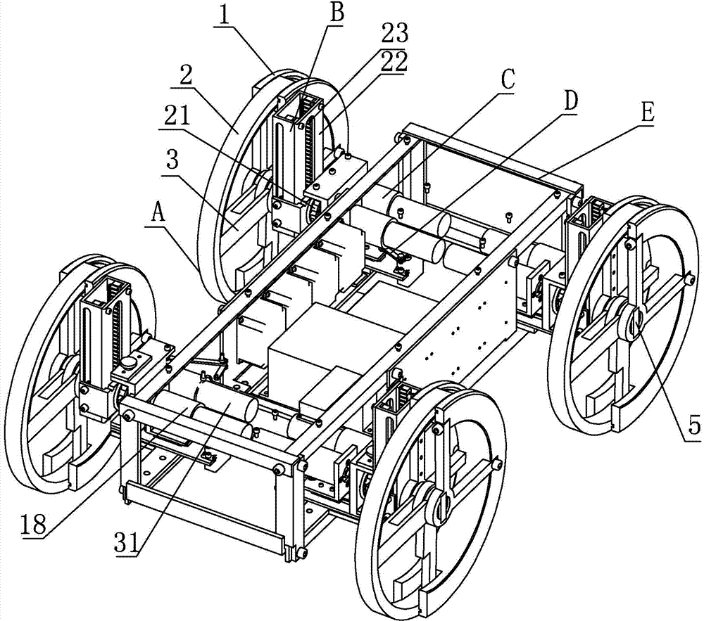
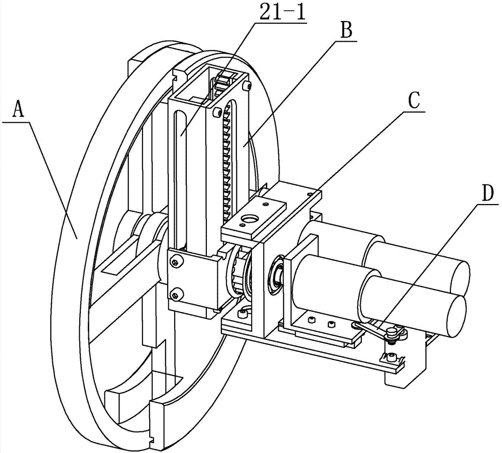
[0017] Specific implementation mode one: as Figure 1~6 As shown, the wheel-foot conversion mobile robot system of this embodiment includes a robot frame E and four wheel-foot conversion mechanisms, and four wheel-foot conversion mechanisms are installed in a matrix on the robot frame, and each wheel-foot conversion mechanism includes a wheel-foot conversion body A. Lifting mechanism B, rotating mechanism C and switching mechanism D;
[0018] The wheel-foot conversion mobile robot system includes a wheel-foot conversion body A, a lifting mechanism B, a rotating mechanism C and a switching mechanism D;
[0019] The wheel-foot conversion body A includes a fixed half-wheel 1, a movable half-wheel 2, a single banner 3, a central shaft 4, a first limit block 5 and a spring 6, and the central shaft 4 is installed at the center of the fixed half-wheel 1 through a first bearing , one end of the central shaft 4 is fixedly connected and axially locked by the first limit block 5, the ot...
specific Embodiment approach 2
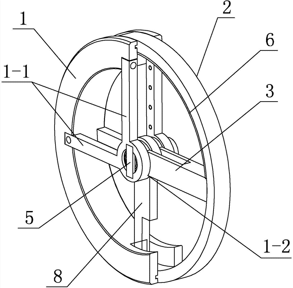
[0023] Specific implementation mode two: as image 3 As shown, two fixed banners 1-1 are arranged on the fixed half-wheel 1 in this embodiment, and the two fixed banners 1-1 are arranged at right angles. Such setting ensures the rigidity of the fixed half-wheel 1, and no serious deformation will occur under the condition of radial force. Designing the fixed banner 1-1 and the fixed half-wheel 1 as two parts also reduces the processing cost. difficulty and cost. Other components and connections are the same as those in the first embodiment.
specific Embodiment approach 3
[0024] Specific implementation mode three: as image 3As shown, the wheel-foot conversion body No. A of this embodiment includes a stopper 6 and a movable banner 8. The stopper 6 is arranged on the inner wall of the movable half-wheel 2, and a notch is processed at the joint of the two fixed banners 1-1. 1-2. When switching the wheel state, the single banner 3 is limited in the horizontal position by the notch 1-2, the upper end of the single banner 3 is in contact with the stopper 6, and the movable banner 8 is vertically arranged on the wheel foot conversion body A. In the lower half, one end of the movable banner 8 is fixedly connected with the central axis 4, and the other end of the movable banner 8 is fixedly connected with one end of the movable half-wheel 2. With such a design, it is easy to see that the single-span 3 is a follower spoke, which can rotate with the movable half-wheel 2 when the wheel foot is converted, and plays a role in improving the rigidity of the m...
PUM
 Abstract
Description
Claims
Application Information
 - R&D
- Intellectual Property
- Life Sciences
- Materials
- Tech Scout
- Unparalleled Data Quality
- Higher Quality Content
- 60% Fewer Hallucinations
Browse by: Latest US Patents, China's latest patents, Technical Efficacy Thesaurus, Application Domain, Technology Topic, Popular Technical Reports.
© 2025 PatSnap. All rights reserved.Legal|Privacy policy|Modern Slavery Act Transparency Statement|Sitemap|About US| Contact US: help@patsnap.com


