Electro-absorption modulator with integrated control loop for linearization and temperature compensation
a technology of linearization and temperature compensation, applied in the field of electroabsorption modulators, can solve the problems of significant power loss, loss of half of the drive voltage, and packaging approaches that do not meet this requiremen
- Summary
- Abstract
- Description
- Claims
- Application Information
AI Technical Summary
Benefits of technology
Problems solved by technology
Method used
Image
Examples
first embodiment
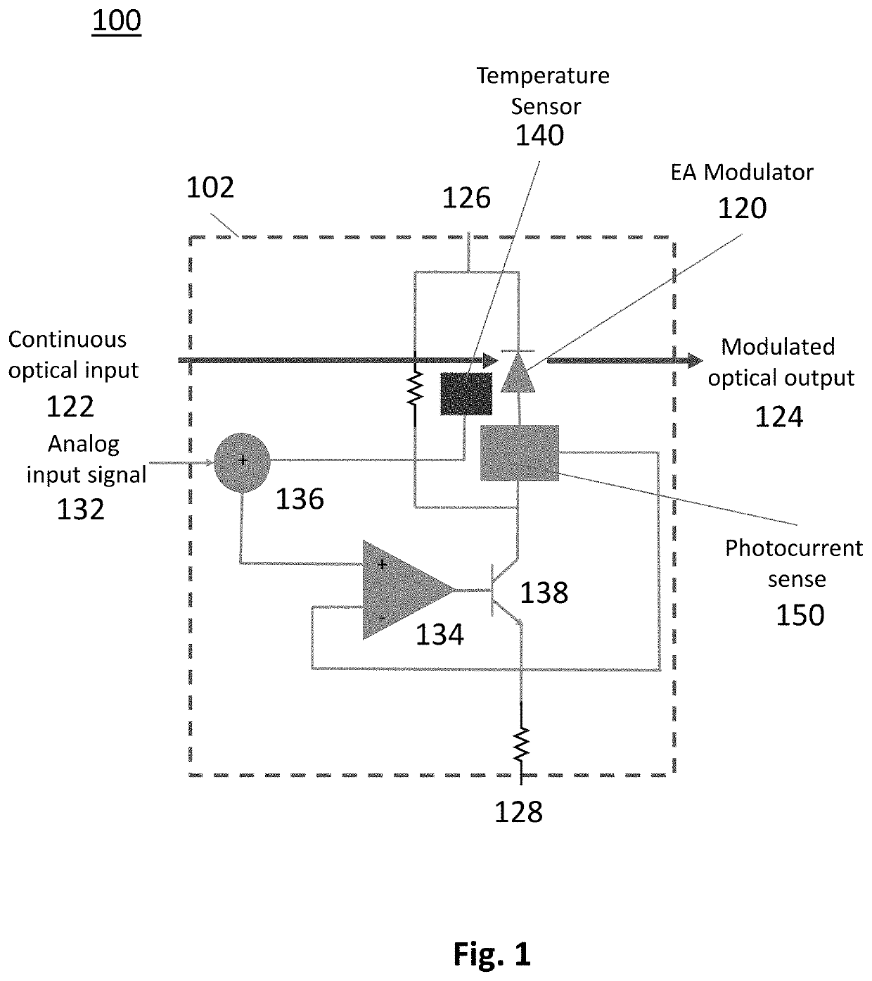
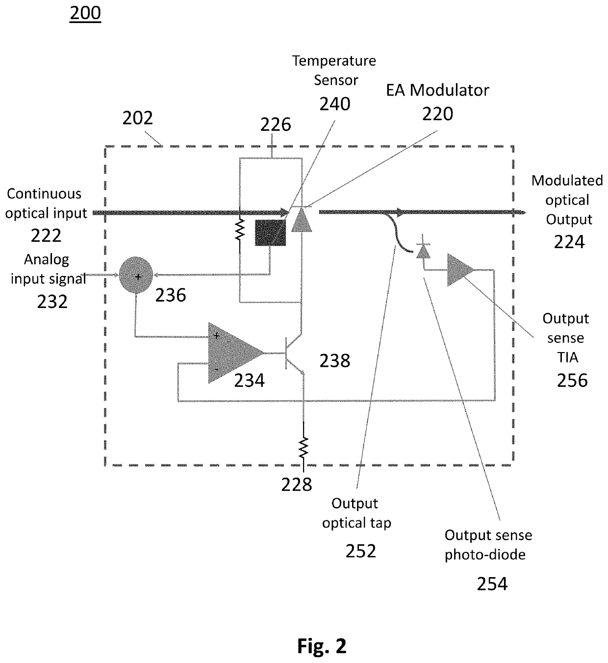
[0034]An electro-photonic integrated circuit 100 comprising an electro-absorption modulator 120 and monolithically integrated fast feedback control loop circuitry is shown in FIG. 1. Elements of the electro-photonic integrated circuit 100 are monolithically fabricated on a device area 102 of the substrate, and comprise the electro-absorption modulator 120 and integrated driver and control circuitry elements. The electro-absorption modulator 120 has an optical input 122 for receiving continuous wave (CW) optical input and an optical output 124 for outputting a modulated optical output. For example, the CW optical input may be provided by a discrete or integrated laser diode (not illustrated) that is coupled to the electro-absorption modulator via an optical waveguide and / or a spot size converter (SSC). The optical output 124 may also comprise a SSC for coupling to other optical components. Electrical terminals 126 and 128 of the electro-optical modulator are provided for applying a ...
third embodiment
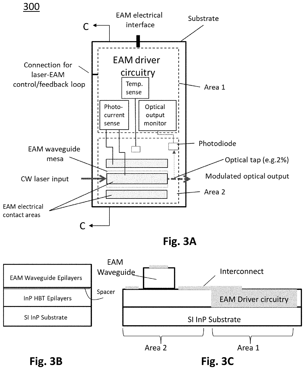
[0041]By way of example, to illustrate how an EAM and its driver and control circuitry can be monolithically integrated in practice, i.e. to place optical and electronic components in close proximity to reduce interconnect lengths, FIG. 3A shows a schematic plan view of an EAM with a monolithically integrated EAM driver comprising control circuitry of a The electronic circuitry comprising the EAM driver and control circuitry is fabricated on a first area (Area 1) of the substrate. The EAM is fabricated on a second area (Area 2) of the substrate. As illustrated schematically, to monitor the optical output of the EAM, the EAM driver and control circuitry comprises at least one of a) a photocurrent sense for indirectly monitoring the optical output of the EAM, and b) an optical tap and a photodiode for directly monitoring the optical output of the EAM, or c) a combination of optical and electronic components for direct and indirect monitoring of the EAM output.
[0042]In the embodiment ...
fourth embodiment
[0044]FIG. 4 shows a schematic plan view of an electro-absorption modulated laser (EML) comprising an EAM and monolithically integrated EAM driver and control circuitry of a In this embodiment, the EAM chip comprising the integrated EAM and its driver and control circuitry comprises a photo current sense for monitoring the EAM output, e.g. using a driver and control circuit as illustrated schematically in FIG. 1. The laser, e.g. a DFB semiconductor laser with a surface etched grating, is operated in CW mode and may comprise discrete or integrated laser control circuitry. The laser may include a photodetector for power monitoring, e.g. a photodiode for back-facet power monitoring (as illustrated schematically). Alternatively, it may include some sort of front-facet optical tap and a photodetector for front-facet power monitoring. In this example embodiment, the EAM driver and control circuitry also provides for a connection (labelled laser-EAM control loop) between the EAM driver an...
PUM
| Property | Measurement | Unit |
|---|---|---|
| impedance | aaaaa | aaaaa |
| drive voltage | aaaaa | aaaaa |
| bias voltage | aaaaa | aaaaa |
Abstract
Description
Claims
Application Information
 - R&D
- Intellectual Property
- Life Sciences
- Materials
- Tech Scout
- Unparalleled Data Quality
- Higher Quality Content
- 60% Fewer Hallucinations
Browse by: Latest US Patents, China's latest patents, Technical Efficacy Thesaurus, Application Domain, Technology Topic, Popular Technical Reports.
© 2025 PatSnap. All rights reserved.Legal|Privacy policy|Modern Slavery Act Transparency Statement|Sitemap|About US| Contact US: help@patsnap.com


