Eyepiece device for a surgical instrument

a surgical instrument and eyepiece technology, applied in the field of eyepiece devices for surgical instruments, can solve the problems of chromatic aberration, inevitably occurring in optical imaging systems, imaging errors, and materials with abnormal dispersion that are often significantly more brittle than conventional glasses, and achieve the effect of improving the temperature resistance of the eyepiece devi

Active Publication Date: 2020-05-05
OLYMPUS WINTER & IBE
View PDF27 Cites 0 Cited by
  • Summary
  • Abstract
  • Description
  • Claims
  • Application Information

AI Technical Summary

Benefits of technology

[0008]It is an object to indicate an eyepiece device for a surgical instrument, an eyepiece comprising an eyepiece device and a surgical instrument having an eyepiece, wherein a further objective is to improve a temperature resistance of the eyepiece device, the eyepiece and the surgical instrument, especially at the temperatures that typically occur during autoclaving.
[0012]In order to prevent damage to the optical unit, such as to the second optical element, the eyepiece frame can comprise an expansion chamber for the second optical element, wherein the expansion chamber extends an installation space provided for the optical unit in a radial direction. The first optical element can be in addition mechanically accommodated in the eyepiece frame. In other words, there can be at least one mechanical connection element between the eyepiece frame and the first optical element for accommodating the optical unit in the eyepiece frame.
[0013]The forces occurring as a consequence of the heat treatment and the resulting material expansion therefore occur between the first optical element and the eyepiece frame. The second optical element, which is frequently manufactured from a mechanically more brittle material, is not exposed to any mechanical load or is exposed to a significantly lower mechanical load. As a result, the temperature resistance of the eyepiece device is significantly improved, especially with regard to the temperatures occurring during an autoclave treatment.
[0015]In addition, a mechanical contact can be avoided between the second optical element and the eyepiece frame due to the expansion chamber which can extend the installation space provided for the optical unit in a radial direction. Said second optical element expands into the existing expansion chamber during the temperature treatment. This measure improves the temperature resistance of the eyepiece device.
[0017]A region of an optical element can be a cylindrical region, in which the optical element extends in the radial direction and in the longitudinal direction, i.e. along the optical axis. In other words, the diameter of the eyepiece frame can be extended along the entire length of the second optical element with respect to the adjoining regions. This can avoid a mechanical contact between the second optical element and an inside of the eyepiece frame.
[0018]A mechanical contact between the second optical element and an inside of the eyepiece frame can also be avoided in that the second optical element can have a smaller diameter than the first optical element, such as where the optical elements are lenses.

Problems solved by technology

Imaging errors, for example chromatic aberration, inevitably occur in optical imaging systems.
In addition, materials with abnormal dispersion are frequently significantly more brittle than conventional glasses.

Method used


Image

  • Eyepiece device for a surgical instrument
  • Eyepiece device for a surgical instrument
  • Eyepiece device for a surgical instrument

Examples


Embodiment Construction

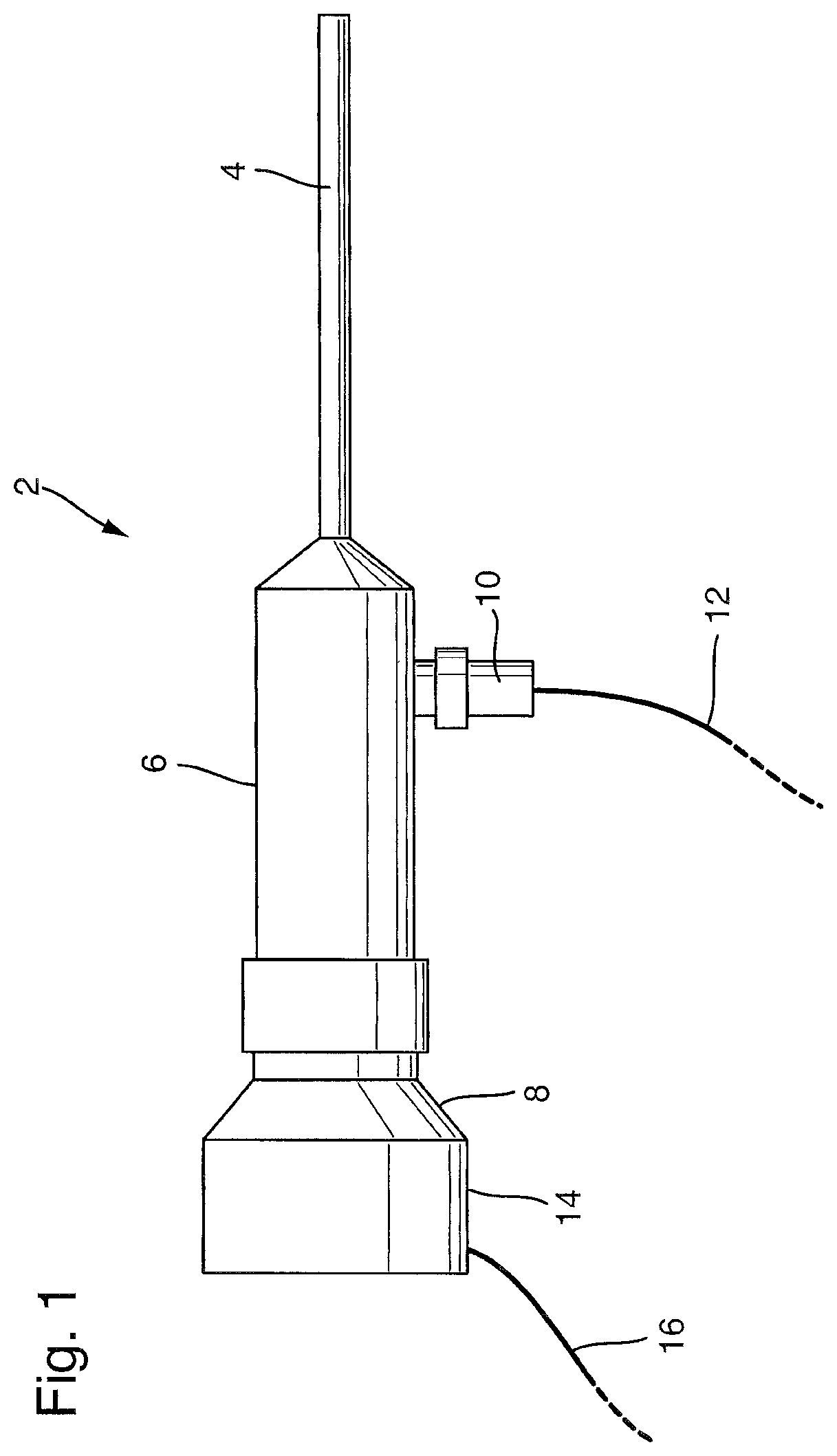
[0037]FIG. 1 shows a schematic and simplified side view of a surgical instrument 2, by way of example an endoscope. At its distal end, the endoscope comprises a tubular shaft 4 having optics which make it possible to observe an operation and examination field which is located distally before a free end of the shaft 4. The shaft 4 opens out into a housing 6 which has an eyepiece cap 8 at the proximal end. The housing 6 is used to handle the surgical instrument 2. Located laterally on the housing 6 is a light source 10, for example a LED light source. This is connected via a connecting cable 12 to a suitable power supply 12.

[0038]A camera head 14, which is shown schematically, having an eyepiece adapter (not shown) is arranged on the eyepiece cap 8. The camera head 14 captures the light exiting from the eyepiece (not shown) of the surgical instrument 2 with suitable optics and images the light on an optical area sensor, for example a CCD or CMOS chip. The camera head 14 is supplied wi...


PUM


Abstract

An eyepiece device for a surgical instrument, the eyepiece device including: an eyepiece frame; and at least one optical unit accommodated in the eyepiece frame, wherein the at least one optical unit comprises at least one first optical element and a second optical element connected with the at least one first optical element, wherein the second optical element is formed from a second material with abnormal dispersion and the first and the second optical elements together correct chromatic aberration; wherein the eyepiece frame comprises an expansion chamber for at least the second optical element, the expansion chamber forming an installation space for at least the second optical element in a radial direction.

Description

CROSS-REFERENCE TO RELATED APPLICATION[0001]The present application is a continuation of PCT / EP2016 / 052114 filed on Feb. 2, 2016, which is based upon and claims the benefit to DE 10 2015 203 351.1 filed on Feb. 25, 2015, the entire contents of each of which are incorporated herein by reference.BACKGROUNDField[0002]The present application relates to an eyepiece device for a surgical instrument, such as an endoscope, wherein the eyepiece device comprises an eyepiece frame and at least one optical unit which is accommodated in the eyepiece frame, wherein the optical unit comprises at least one first optical element and a second optical element connected therewith, wherein the second optical element is manufactured from a second material with abnormal dispersion and the first and the second optical elements together form an optical unit which is corrected in respect of chromatic aberration. The present application also relates to an eyepiece comprising such an eyepiece device and a surg...

Claims


Application Information

Patent Timeline
Patent Type & Authority Patents(United States)
IPC IPC(8): A61B1/00G02B7/02G02B27/00G02B25/00G02B23/24A61B1/06A61B90/00A61B1/05
CPCA61B1/0011G02B23/2453G02B7/025G02B25/001G02B27/0025A61B1/00195G02B7/028A61B1/00006A61B1/0684A61B1/051A61B2090/0813
Inventor KIEDROWSKI, GREGOR
Owner OLYMPUS WINTER & IBE
Why Eureka
Try Eureka