Spiral wound gasket
a gasket and spiral technology, applied in the direction of engine seals, flanged joints, pipe joints, etc., can solve the problems of difficult and likely formation of gap between the protruding end portions of the filler member, and achieve the effect of sufficient sealability for the flang
- Summary
- Abstract
- Description
- Claims
- Application Information
AI Technical Summary
Benefits of technology
Problems solved by technology
Method used
Image

Examples
example 1
Production and Evaluation of Test Gaskets Using Hoop Member Having W-Shape in Cross Section
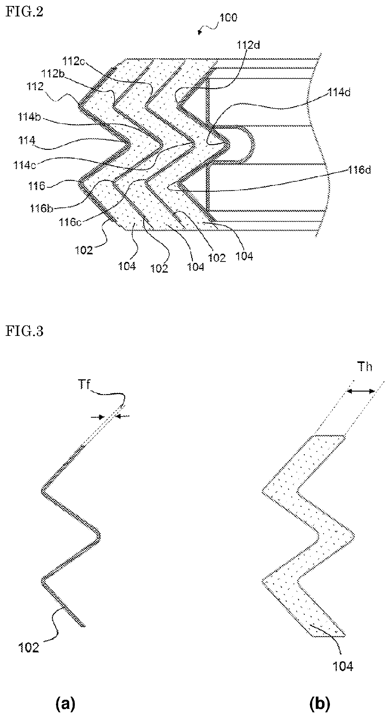
[0056]A hoop member having a W-shape in cross section was produced by drawing SUS304 band steel with a width of 7.1 mm and an initial thickness (Th) of 0.13 mm. Note that, in the thus produced hoop member having the W-shape in cross section, all of the angles constituting the bent portions were the same. On the other hand, various pieces of expanded graphite tape with a width of 7.5 mm and an initial thickness (Tf) of 0.18 mm to 2.08 mm were prepared, and among these, those pieces whose 25% compressive load P in conformity with JIS 6254 was within the range of 5 MPa to 9 MPa were selected. Then, each of the selected pieces of expanded graphite tape was used as a filler member, and laminated on one surface of the hoop member having the W-shape in cross section, and the laminate was spirally wound three turns while a load of 15 kgf was applied thereto using a pressure roll, to produce a test gas...
example 2
Production and Evaluation of Test Gaskets Using Hoop Member Having V-shape in Cross Section
[0067]Filler members having various 25% compressive loads P and percentages Tr with respect to the thicknesses were produced, and a hoop member having a V-shape in cross section was produced by drawing SUS304 band steel similar to that of Example 1. That is to say, test gaskets were produced in the same manner as in Example 1 except that the hoop member having a different shape in cross section than that of Example 1 was used.
[0068]With respect to the obtained test gaskets, the flatness was evaluated based on the surface roughness Rz of their gasket faces, and whether or not a gap was present was visually observed, in the same manner as in Example 1. As a result, it was confirmed that test gaskets whose surface roughness Rz was within the range of 30 μm to 200 μm were favorable as gaskets.
[0069]Moreover, with respect to the test gaskets whose gasket faces had a surface roughness Rz within the ...
example 3
Production and Evaluation of Test Gaskets with Filler Members Being Changed
[0070]Except that various pieces of non-asbestos paper made of nonmetal with a width of 7.5 mm and an initial thickness (Tf) of 0.18 mm to 2.08 mm were used as filler members instead of the pieces of expanded graphite tape, test gaskets were produced in the same manner as in Example 1. That is to say, filler members having various 25% compressive loads P and percentages Tr with respect to the thicknesses were produced, and a hoop member having a W-shape in cross section was produced.
[0071]With respect to the obtained test gaskets, the flatness was evaluated based on the surface roughness Rz of their gasket faces, and whether or not a gap was present was visually observed, in the same manner as in Example 1. As a result, it was confirmed that test gaskets whose surface roughness Rz was within the range of 30 μm to 200 μm were favorable as gaskets.
[0072]Moreover, with respect to the test gaskets whose gasket fa...
PUM
| Property | Measurement | Unit |
|---|---|---|
| surface roughness Rz | aaaaa | aaaaa |
| compressive load | aaaaa | aaaaa |
| thickness | aaaaa | aaaaa |
Abstract
Description
Claims
Application Information
 - R&D
- Intellectual Property
- Life Sciences
- Materials
- Tech Scout
- Unparalleled Data Quality
- Higher Quality Content
- 60% Fewer Hallucinations
Browse by: Latest US Patents, China's latest patents, Technical Efficacy Thesaurus, Application Domain, Technology Topic, Popular Technical Reports.
© 2025 PatSnap. All rights reserved.Legal|Privacy policy|Modern Slavery Act Transparency Statement|Sitemap|About US| Contact US: help@patsnap.com