Vane pump

a technology of vane pump and valve body, which is applied in the direction of rotary/oscillating piston pump components, machines/engines, liquid fuel engines, etc., can solve the problems of rotor and cover being more likely to wear, and achieve the effect of convenient formation, easy protection from thrust load, and sufficient sealing of sliding interfa

Active Publication Date: 2021-06-15
TAIHO INDUSTRIES CO LTD
View PDF20 Cites 0 Cited by
  • Summary
  • Abstract
  • Description
  • Claims
  • Application Information

AI Technical Summary

Benefits of technology

[0010]At least one of the inner surface of the housing and the end face of the peripheral wall portion of the rotor has an oil groove. The oil groove directly or indirectly communicates with the oil chamber of the rotor. The lubricating oil in the oil chamber of the rotor therefore directly or indirectly flows into the oil groove. According to the vane pump of the present invention, an oil film is therefore easily formed in the sliding interface. Accordingly, sufficient sealability of the sliding interface is easily provided, and the sliding interface is easily protected from thrust load. According to the vane pump of the present invention, members such as the biasing portions and the sliding member of Patent Document 1 need not be additionally disposed in order to provide sufficient sealability of the sliding interface. An increase in number of parts is thus restrained.

Problems solved by technology

If the oil film becomes discontinuous, the rotor and the inner surface of the cover tend to be in sliding contact with each other, and the rotor and the cover are therefore more likely to wear.

Method used


Image

  • Vane pump
  • Vane pump
  • Vane pump

Examples


first embodiment

[0020][Configuration of Vane Pump]

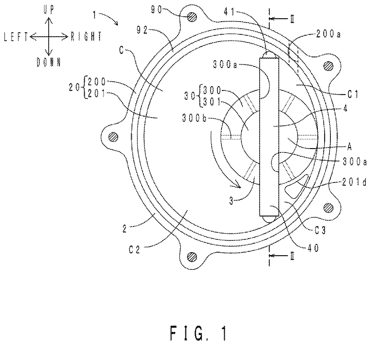
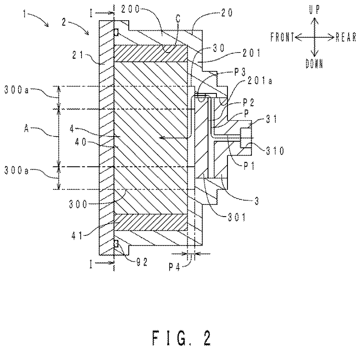
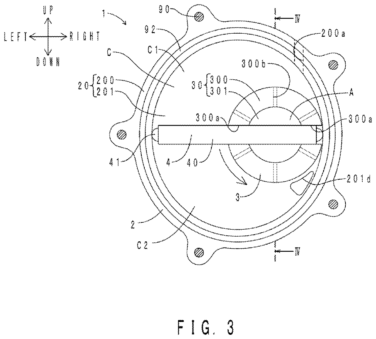
[0021]First, the configuration of a vane pump of an embodiment will be described. FIG. 1 shows a radial section of the vane pump of the present embodiment. FIG. 2 is a sectional view taken along line II-II in FIG. 1. FIG. 3 shows a radial section of the vane pump. FIG. 4 is a sectional view taken along line IV-IV in FIG. 3. FIG. 1 corresponds to a section taken along line I-I in FIG. 2. FIG. 3 corresponds to a section taken along line III-III in FIG. 4. A rotor 3 and a vane 4 of a vane pump 1 shown in FIGS. 3 and 4 have been rotated (advanced) by 90° with respect to those of the vane pump 1 shown in FIGS. 1 and 2. The vane pump 1 is a negative pressure source of a booster of a brake device. The vane pump 1 is driven to rotate by a camshaft (not shown). As shown in FIGS. 1 to 4, the vane pump 1 includes a housing 2, the rotor 3, and the vane 4.

[0022](Housing 2)

[0023]The housing 2 is fixed to a side surface of an engine (not shown). The housing 2 incl...

second embodiment

[0048]A vane pump of the present embodiment is different from the vane pump of the first embodiment in that the oil grooves extend in the circumferential direction rather than in the radial direction. Only the difference will be described below. FIG. 6 shows a radial section of the vane pump of the present embodiment. Portions corresponding to those in FIG. 1 are denoted with the same reference characters. As shown in FIG. 6, a plurality of oil grooves 300c are formed concentrically about the radial center of the rotor 3, as viewed from the front. Each of the plurality of oil grooves 300c extends in the circumferential direction in the shape of an endless ring about the radial center of the rotor 3. The plurality of oil grooves 300c indirectly communicate with each other through a sliding interface. The plurality of oil grooves 300c indirectly communicate with an oil chamber A and a pump chamber C through the sliding interface.

[0049]Regarding the portions having the same configurati...


PUM


Abstract

A vane pump including: a housing having a pump chamber; a rotor having a cylindrical peripheral wall portion accommodated in the pump chamber and having a pair of vane holding grooves facing each other in a diameter direction, and an oil chamber defined inside the peripheral wall portion to store lubricating oil; and a vane that is held in the pair of vane holding grooves and moves across the oil chamber in the diameter direction, is provided. At least one of an inner surface of the housing and an end face of the peripheral wall portion, which together with the inner surface defines a sliding interface, has an oil groove for the lubricating oil.

Description

TECHNICAL FIELD[0001]The present invention relates to vane pumps that are driven by, e.g., an engine of a vehicle.BACKGROUND ART[0002]Vane pumps include a rotor, a vane or vanes, and a housing. The housing includes a housing body having a recess, and a cover that seals the recess. A pump chamber is defined in the housing. The rotor and the vane(s) are rotatably accommodated in the pump chamber. An oil film is formed in a sliding interface between one axial end face (thrust surface) of the rotor and the inner surface of the cover. If the oil film becomes discontinuous, the rotor and the inner surface of the cover tend to be in sliding contact with each other, and the rotor and the cover are therefore more likely to wear.[0003]In this regard, Patent Document 1 discloses a vane pump having a plurality of biasing portions (coil springs). The plurality of biasing portions bias a rotor in the direction in which a thrust surface is separated from the inner surface of a cover (the direction...

Claims


Application Information

Patent Timeline
Patent Type & Authority Patents(United States)
IPC IPC(8): F03C2/00F03C4/00F04C2/00F04C18/00F04C18/344F04C25/02F04C29/02F04C27/00
CPCF04C18/344F04C18/3442F04C25/02F04C27/001F04C29/021F04C29/025F04C29/028F04C27/005F04C2230/92F04C2240/20F04C2240/30F04C2250/20
Inventor IKEDA, SATOSHINAKAMUTA, KEN
Owner TAIHO INDUSTRIES CO LTD
Why Eureka
Try Eureka