Tank and tank manufacturing method

a manufacturing method and tank technology, applied in the direction of sealing, manufacturing tools, transportation and packaging, etc., can solve the problems of preventing the sealing of sufficient sealability between the mouth portion and the ferrule member, and achieve the effect of sufficient sealability, sufficient sealability and sufficient sealability

Active Publication Date: 2014-09-23
TOYOTA JIDOSHA KK
View PDF15 Cites 0 Cited by
  • Summary
  • Abstract
  • Description
  • Claims
  • Application Information

AI Technical Summary

Benefits of technology

[0009]It is therefore an advantage of the present invention to provide a tank and a method of manufacturing a tank in which an insert ring is prevented from being fixed in an off-center state due to flow of resin at the time of molding a liner to thereby allow securing of sufficient sealability between a mouth portion and a ferrule member.
[0010]In accordance with an aspect of the invention, there is provided a tank including an O-ring between a cylindrical mouth portion which is formed in a resin liner forming a tank body which is to be filled with gas and a ferrule member which is mounted on an inner peripheral side of the mouth portion, wherein an insert ring which is insert-molded at the time of molding the resin liner is provided within the mouth portion, the insert ring including a plurality of communication holes which communicate between the inner peripheral side and an outer peripheral side of the insert ring.
[0011]In accordance with another aspect of the invention, there is provided a method of manufacturing a tank including an O-ring between a cylindrical mouth portion which is formed in a resin liner forming a tank body which is to be filled with gas, and a ferrule member which is mounted on an inner peripheral side of the mouth portion, including insert-molding an insert ring within the mouth portion at the time of molding the resin liner, the insert ring including a plurality of communication holes which communicate between the inner peripheral side and an outer peripheral side of the insert ring. By providing the communication holes, it is easy to equalize the charging quantity of resin with respect to the inner peripheral side and the outer peripheral side of the insert ring at the time of molding a resin liner. When the uniform charging quantity of resin hardens at a substantially uniform thickness along the circumferential direction, the insert ring is fixed at substantially the center portion with respect to the center axis of the cylindrical mouth portion. Consequently, sufficient sealability can be ensured between the mouth portion and the ferrule member.
[0012]According to the present invention, it is possible to provide a tank and a method of manufacturing a tank in which an insert ring is prevented from being fixed in an off-center state due to flow of resin at the time of molding a liner, to thereby allow securing of sufficient sealability between a mouth portion and a ferrule member.

Problems solved by technology

However, with regard to the insert ring which is used for the tank described in JP 2008-303966 A, there is a problem that there are cases in which, at the time of molding the liner, the volume of a resin (charging quantity) charging the inner peripheral side of the insert ring differs from the volume of a resin (charging quantity) charging the outer peripheral side of the insert ring, and consequently the insert ring is fixed in a displaced (off-center) state with respect to the center axis of the cylindrical mouth portion.
Further, when the thickness of the resin provided between the insert ring and the mouth portion is non-uniform, the liner (mainly the mouth portion) is deformed due to a reaction force of the O-ring, thereby preventing securing of sufficient sealability between the mouth portion and the ferrule member.

Method used


Image

  • Tank and tank manufacturing method
  • Tank and tank manufacturing method
  • Tank and tank manufacturing method

Examples


Embodiment Construction

[0018]A preferred embodiment of the present invention will be described in detail with reference to the accompanying drawings.

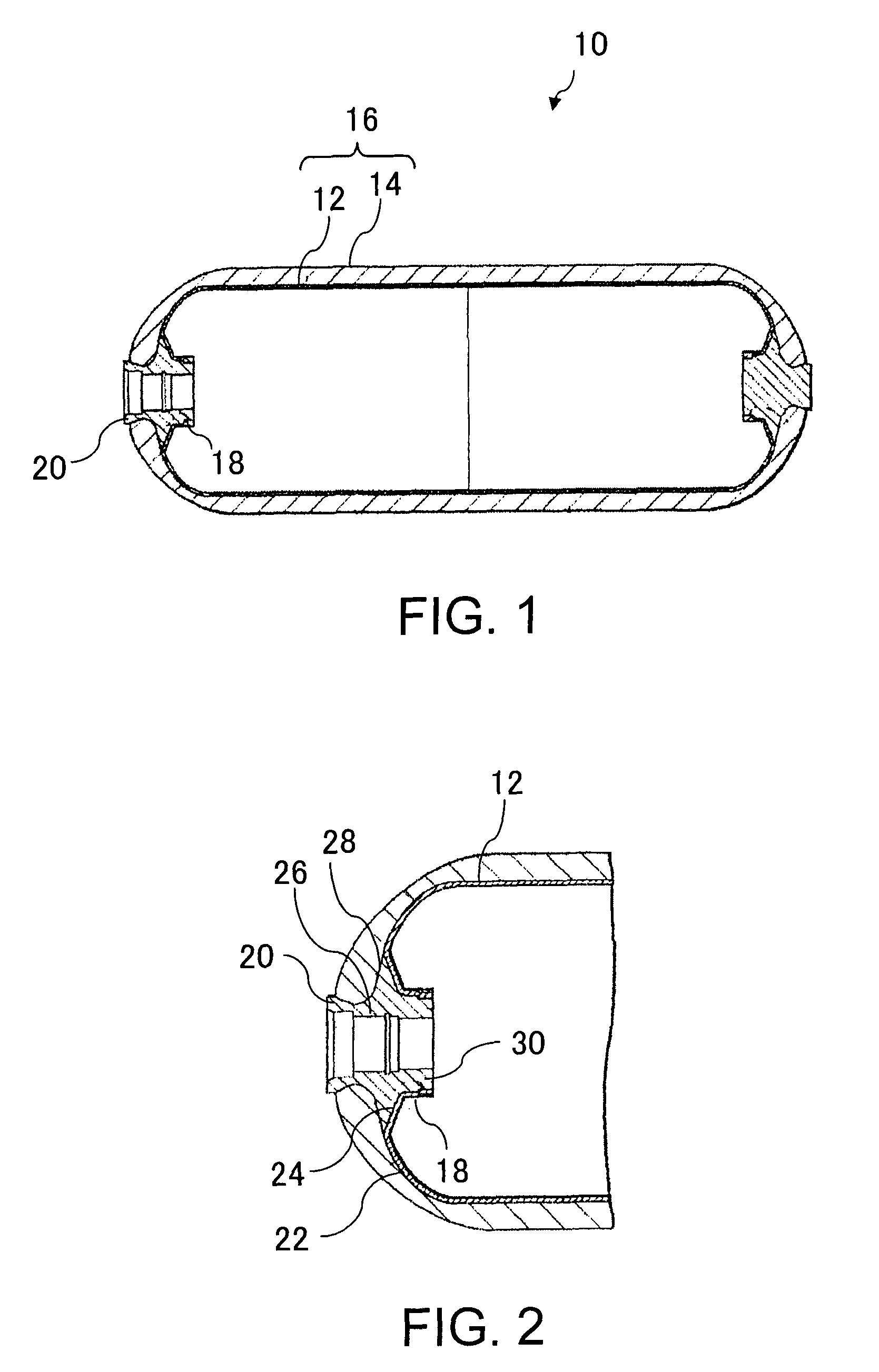
[0019]FIG. 1 is a cross sectional view schematically illustrating an example structure of a tank according to the present embodiment. A tank 10 illustrated in FIG. 1 is to be charged with high pressure gas and store the high pressure gas therein, and includes a tank body 16 which is formed of a liner 12 made of a resin or a resin liner (a mounting subject) and a fiber reinforced resin layer 14 which is formed of a glass fiber, a carbon fiber, and so on and which covers the outer peripheral side of the resin liner 12.

[0020]At each end of the tank body 16, a ferrule member 20 is mounted on a mouth portion 18 formed on the resin liner 12. Here, the side of the tank body 16 having the ferrule member 20 to which a valve can be attached is referred to as a valve side, and the opposite side is referred to as an end side.

[0021]FIG. 2 is a cross sectional view schemat...


PUM

PropertyMeasurementUnit
pressureaaaaaaaaaa
volumeaaaaaaaaaa
timeaaaaaaaaaa

Abstract

The present invention provides a tank including an O-ring 34 between a cylindrical mouth portion 18, which is formed in a resin liner 12 forming a tank body which is to be filled with gas, and a ferrule member 20 which is mounted on an inner peripheral side of the mouth portion 18. An insert ring 36 which is insert-molded at the time of molding the resin liner 12 is provided within the mouth portion 18. The insert ring 36 includes a plurality of communication holes 38 which communicate between the inner peripheral side and an outer peripheral side thereof.

Description

PRIORITY INFORMATION[0001]This application claims priority to Japanese Patent Application No. 2009-240011, filed on Oct. 19, 2009, which is incorporated herein by reference in its entirety.TECHNICAL FIELD[0002]The present invention relates to technology of a high-pressure tank.BACKGROUND ART[0003]In high-pressure tanks which are to be charged with gas such as hydrogen, gas tightness is important. Concerning this type of gas tank, there is known, as technology for establishing a seal between a mouth portion formed on a resin liner forming a tank body and a ferrule member fitted on the inner peripheral side of the mouth portion, technology in which an O-ring is mounted in a groove portion formed on the liner and an insert ring is provided on the outer periphery of the liner for clamping the O-ring in the radially inward direction, thereby establishing a seal between the mouth portion and the ferrule member. (See JP 2008-303966 A, for example).[0004]Further, there is also known, as tec...

Claims


Application Information

Patent Timeline
Patent Type & Authority Patents(United States)
IPC IPC(8): B65D53/00F17C1/00B65D53/02
CPCF17C1/00F17C2203/0604F17C2203/0619F17C2201/0109B65D53/02F17C2205/0397Y02E60/321F17C2221/012F17C2203/0673F17C2201/035F17C2209/2118F17C2223/0123F17C2260/036F17C2205/0305Y10T29/4998Y02E60/32
Inventor YAMAMOTO, YOSHINORI
Owner TOYOTA JIDOSHA KK
Why Eureka
Try Eureka