
Therapy system for transcutaneous in-vivo tissue engineering

a technology of in-vivo tissue engineering and therapy system, which is applied in the field of two-stage therapy system, can solve the problems of inexactness, high infection risk, and inability to manage or control the penetration depth and distribution of skin tissue, and achieves the effect of simple, quick and precise manner

Active Publication Date: 2020-02-25
EUVAIRA BIOTECHSPTYLTD
View PDF3 Cites 7 Cited by
  • Summary
  • Abstract
  • Description
  • Claims
  • Application Information

AI Technical Summary

Benefits of technology

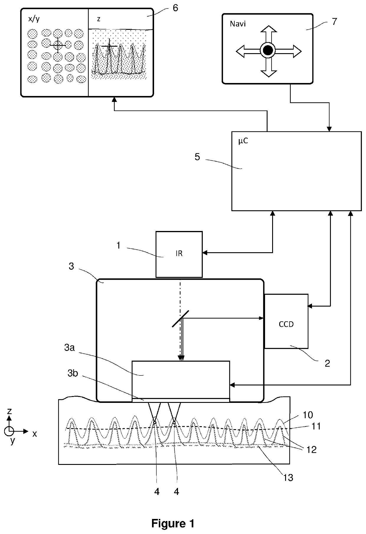
The patent describes a method for identifying the location of small blood vessels called end arterioles in the skin. This is important for accurate identification of abnormal blood flow patterns in the skin that can indicate the presence of certain diseases. The method uses a special optical system with a special element called a Diffractive Optical Element (DOE) or a Digital Mirror Device (DMD) to create multiple focus points simultaneously. This increases the accuracy of identifying the location of the end arterioles. The optical system splits the first light into several focused beam bundles, each focused at a different point in the skin. This results in a much greater energy of the first light compared to using a single focus point, allowing for faster treatment and saving of time.

Problems solved by technology

The aforementioned method of percutaneous collagen induction (“needling”) is invasive, painful, fraught with a high infection risk, and inexact.
In addition, toxic UV-light is applied.
In addition, during topical use of the photosensitizer the penetration depth and distribution in the skin cannot be managed or controlled.
For additional laser-needling a second IR laser light source is required, which entails additional costs for the purchase of the further light source and the expensive optics.
Also for a localisation of the end arterioles in the skin expensive, problem-prone and costly methods are proposed, such as OCT, fluorescence microscopy or fluorescence tomography.

Method used


Image

  • Therapy system for transcutaneous in-vivo tissue engineering
  • Therapy system for transcutaneous in-vivo tissue engineering
  • Therapy system for transcutaneous in-vivo tissue engineering

Examples


Embodiment Construction

The present invention will now be described more fully hereinafter with reference to the accompanying figures, in which some of the embodiments of the invention are shown.

The invention as described hereinafter should not be construed to be limited to the specific embodiments disclosed, with slight modifications and other embodiments intended to be included within the scope of the invention. Although specific terms are employed herein, they are used in a generic and descriptive sense only and not for purposes of limitation.

As used throughout this specification and in the claims which follow, the singular forms “a”, “an” and “the” include the plural form, unless the context clearly indicates otherwise.

The terminology and phraseology used herein is for the purpose of description and should not be regarded as limiting. The use of the terms “comprising”, “containing”, “having”, “including”, and variations thereof used herein, are meant to encompass the items listed thereafter and equival...


PUM

PropertyMeasurementUnit
diameteraaaaaaaaaa
diameteraaaaaaaaaa
wavelengthaaaaaaaaaa

Abstract

The present invention relates to a therapy system for the treatment of the skin and subdermis with light. The system comprises a NIR light source which produces light with a wavelength adapted to an absorption maximum for exciting molecular oxygen in aqueous solution; an image recognition unit for detecting papillary end arterioles and their x-y-z coordinates, wherein a respective depth underneath the skin surface is determined as the z-coordinate by an autofocus function; an optical system for the optical coupling of the light of the NIR light source and the pattern recognition unit to the skin, with a focussing unit to controllably position the light with at least one focus point in the skin; and a control unit to control the NIR light source, the image recognition unit, and the optical system.

Description

This application is a National Phase application filed under 35 U.S.C. § 371 of PCT International Application No. PCT / IB / 2015 / 059007 with an International Filing Date of Nov. 20, 2015, which claims under 35 U.S.C. § 119(a) the benefit of German Application No. 10 2014 017 197.3, filed Nov. 21, 2014, the entire contents of which are incorporated herein by reference.FIELD OF THE INVENTIONThe present invention relates to a two-stage therapy system for the directed production of a collagen matrix in the skin and the subcutaneous tissue, based on a NIR light source or a NIR laser light source.BACKGROUND OF THE INVENTIONDE102011052002284 describes a laser therapy system for the directed production of a collagen matrix in the human skin, which is based in the first instance on a treatment of the skin with a photo-sensitive agent in combination with UVA lights, thereby to specifically ensure a cross-linking of photo-chemical collagen. Secondly, with the described laser therapy system, by a ...

Claims


Application Information

Patent Timeline
Patent Type & Authority Patents(United States)
IPC IPC(8): A61B18/18A61N5/06A61B18/20A61B18/00A61N5/067
CPCA61N5/062A61N5/0616A61B18/203A61N2005/0659A61N2005/0626A61B2018/00452A61N2005/0666A61N2005/0642A61N2005/067A61N2005/0665A61N5/067
Inventor DEPFENHART, MARKUSMÜLLER, JÖRG
Owner EUVAIRA BIOTECHSPTYLTD
Learn More