
Laser-driven high repetition rate source of ultrashort relativistic electron bunches

a relativistic electron and high repetition rate technology, applied in material analysis using wave/particle radiation, instruments, nuclear engineering, etc., can solve the problem of limiting the repetition rate to low levels

Active Publication Date: 2019-12-31
UNIV OF MARYLAND
View PDF6 Cites 0 Cited by
  • Summary
  • Abstract
  • Description
  • Claims
  • Application Information

AI Technical Summary

Problems solved by technology

Typically, these experiments demand laser pulse energies of at least several joules, and consequently existing laser technology limits them to low repetition rates (≤10 Hz).

Method used


Image

  • Laser-driven high repetition rate source of ultrashort relativistic electron bunches
  • Laser-driven high repetition rate source of ultrashort relativistic electron bunches
  • Laser-driven high repetition rate source of ultrashort relativistic electron bunches

Examples


Embodiment Construction

[0061]For the purposes of promoting an understanding of the principles of the present disclosure, reference will now be made to the exemplary embodiments illustrated in the drawings, and specific language will be used to describe the same. It will nevertheless be understood that no limitation of the scope of the present disclosure is thereby intended. Any alterations and further modifications of the inventive features illustrated herein, and any additional applications of the principles of the present disclosure as illustrated herein, which would occur to one skilled in the relevant art and having possession of this disclosure, are to be considered within the scope of the present disclosure.

[0062]The word “exemplary” is used herein to mean “serving as an example, instance, or illustration.” Any embodiment described herein as “exemplary” is not necessarily to be construed as preferred or advantageous over other embodiments.

[0063]It is to be understood that the method steps described ...


PUM

PropertyMeasurementUnit
energyaaaaaaaaaa
energyaaaaaaaaaa
wavelengthsaaaaaaaaaa

Abstract

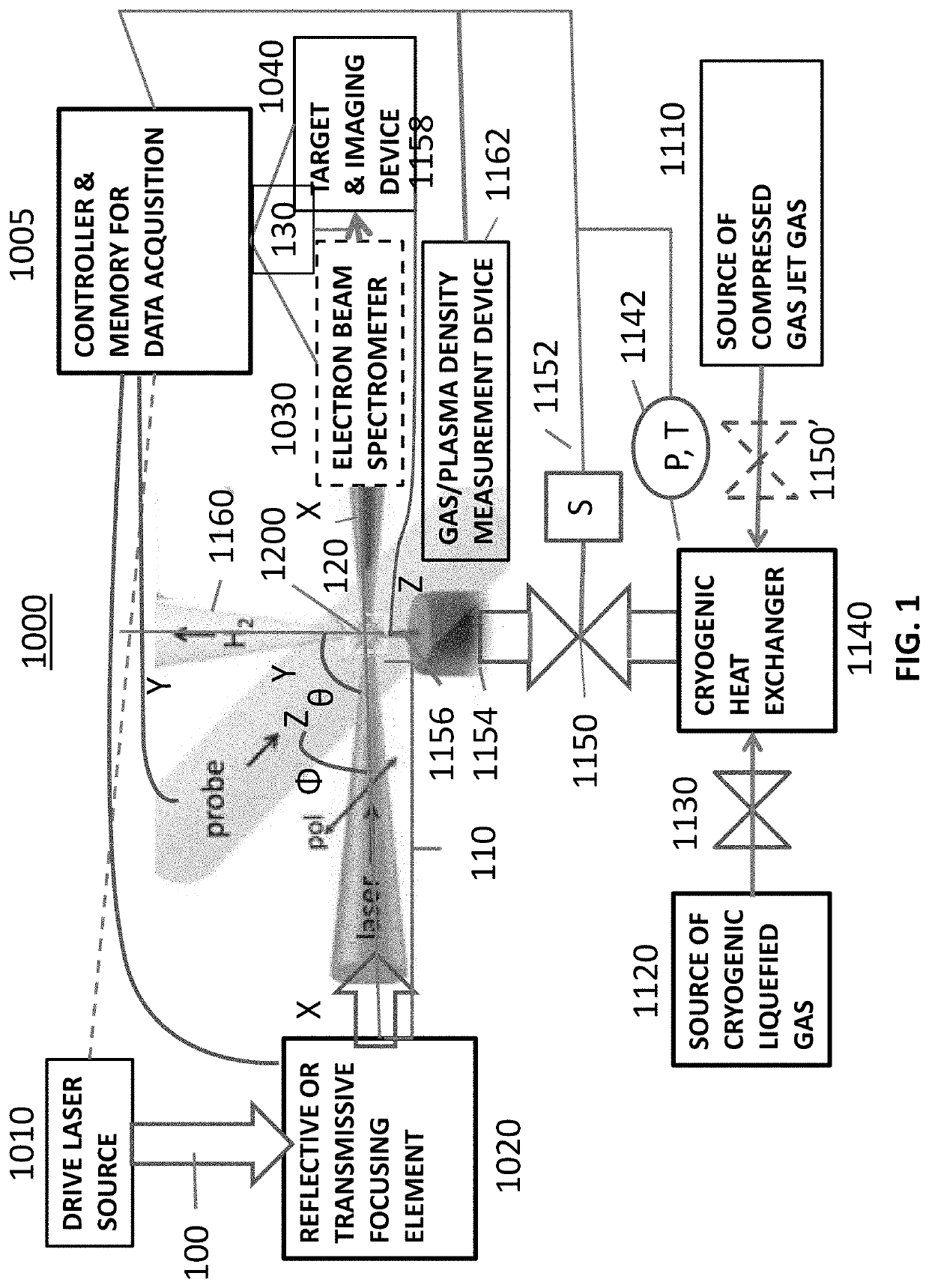
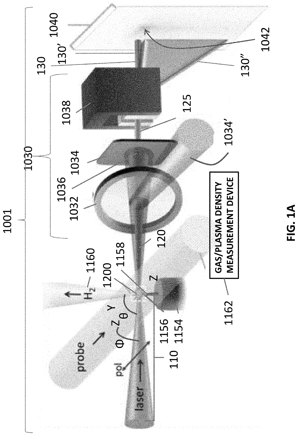
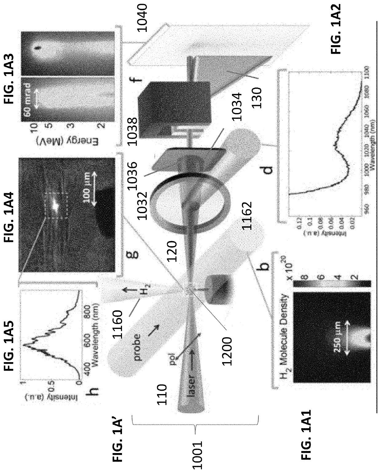
A laser-plasma-based acceleration system includes a focusing element and a laser pulse emission directing a laser beam to the focusing element to such that laser pulses transform into a focused beam and a chamber defining a nozzle having a throat and an exit orifice, emitting a critical density range gas jet from the exit orifice for laser wavelengths ranging from ultraviolet to the mid-infrared. the critical density range gas jet intersects the focused beam at an angle and in proximity to the exit orifice of the nozzle to define a point of intersection between the focused beam and the critical density range gas jet. In intersection with the critical density range gas jet, the pulsed focused beam drives a laser plasma wakefield relativistic electron beam. A corresponding method of laser-plasma-based acceleration is also described. The critical density range may include 2×1020 cm−3 to 5×1021 cm−3.

Description

CROSS-REFERENCE TO RELATED APPLICATIONS[0001]This application claims the benefit of, and priority to, U.S. Provisional Patent Application No. 62 / 336,068, filed on May 13, 2016, entitled “LASER-DRIVEN HIGH REPETITION RATE SOURCE OF ULTRASHORT RELATIVISTIC ELECTRON BUNCHES”, by Howard M. Milchberg et al., the entire contents of which are incorporated by reference herein.STATEMENT OF GOVERNMENT SUPPORT[0002]This invention was made with U.S. government support under FA95501310044 awarded by AFOSR; DESC0007970 awarded by DOE; HDTRA11010045 awarded by DTRA; and PHY1301948 awarded by NSF. The U.S. government has certain rights in the invention.BACKGROUND[0003]1. Technical Field[0004]The present disclosure relates to laser-driven acceleration systems and more particularly to laser-driven plasma wave electron acceleration systems.[0005]2. Discussion of Related Art[0006]Laser-driven electron acceleration in plasma has become a well-established field since it was proposed several decades ago [...

Claims


Application Information

Patent Timeline
Patent Type & Authority Patents(United States)
IPC IPC(8): H05G2/00H05H15/00G01N23/00G21K1/00H01J35/00
CPCH05H15/00H05G2/003H05G2/008G21K1/003H01J35/00
Inventor MILCHBERG, HOWARD M.GOERS, ANDREWHINE, GEORGESALEHI, FATHOLAHFEDER, LINUSMIAO, BO
Owner UNIV OF MARYLAND
Learn More