
Initial rotor position detection device and method based on permanent-magnet synchronous motor

a technology of synchronous motor and initial rotor position, which is applied in the direction of dynamo-electric converter control, dynamo-electric gear control, model/simulation control, etc., can solve the problems of high cost, long system development cycle, and inability to provide comprehensive closed-loop test offline simulation, so as to reduce the cost of a test system, the effect of effective and rapid detection of the initial rotor position

Active Publication Date: 2019-12-17
SHENZHEN JINGQUANHUA ELECTRONICS
View PDF1 Cites 0 Cited by
  • Summary
  • Abstract
  • Description
  • Claims
  • Application Information

AI Technical Summary

Benefits of technology

The invention provides a device and method to quickly and accurately detect the initial position of a permanent-magnet synchronous motor using a binary search algorithm. This helps to reduce the cost of the testing system. This invention is useful for developing and testing control systems for such motors.

Problems solved by technology

For high-power power electronic devices such as the permanent-magnet synchronous motor, experimenting directly on physical devices has many inconveniences.
In the early stage of design, although offline simulation can be used to design and detect an initial angle of the permanent-magnet synchronous motor, the offline simulation cannot provide a comprehensive closed-loop test, has high costs, and requires a long system development cycle.
Therefore, how to build an effective, fast and low-cost initial rotor position detection system based on the permanent-magnet synchronous motor is an urgent technical problem to be solved by a person skilled in the art.

Method used


Image

  • Initial rotor position detection device and method based on permanent-magnet synchronous motor
  • Initial rotor position detection device and method based on permanent-magnet synchronous motor
  • Initial rotor position detection device and method based on permanent-magnet synchronous motor

Examples


Embodiment Construction

[0019]The following clearly and completely describes the technical solutions in the embodiments of the present invention with reference to the accompanying drawings in the embodiments of the present invention. Apparently, the described embodiments are merely a part rather than all of the embodiments of the present invention. All other embodiments obtained by a person of ordinary skill in the art based on the embodiments of the present invention without creative efforts shall fall within the protection scope of the present invention.

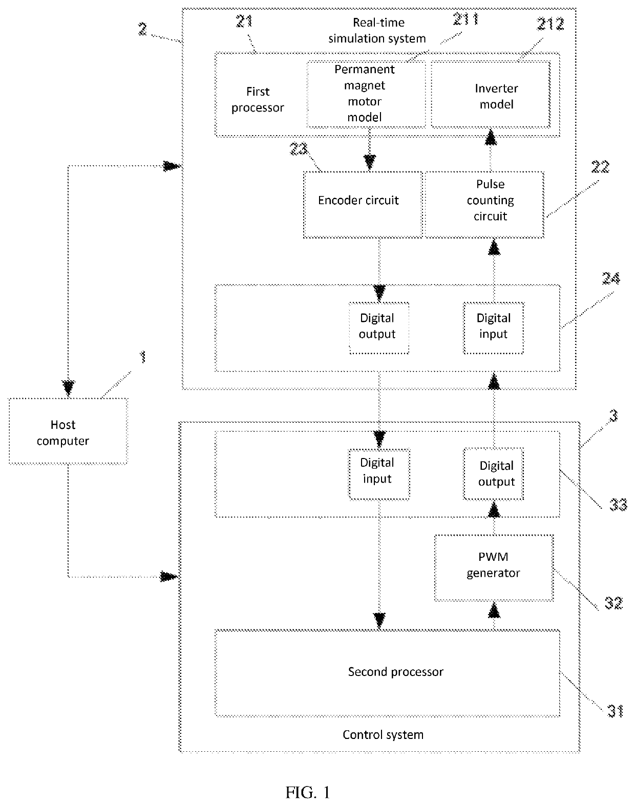
[0020]An objective of the present invention is to provide an initial rotor position detection device and method based on a permanent-magnet synchronous motor, to establish a closed-loop test circuit and use a binary search algorithm to effectively and quickly detect an initial rotor position of a permanent-magnet synchronous motor, finally reducing the cost of a test system.

[0021]To make the foregoing objective, features, and advantages of the present inv...


PUM


Abstract

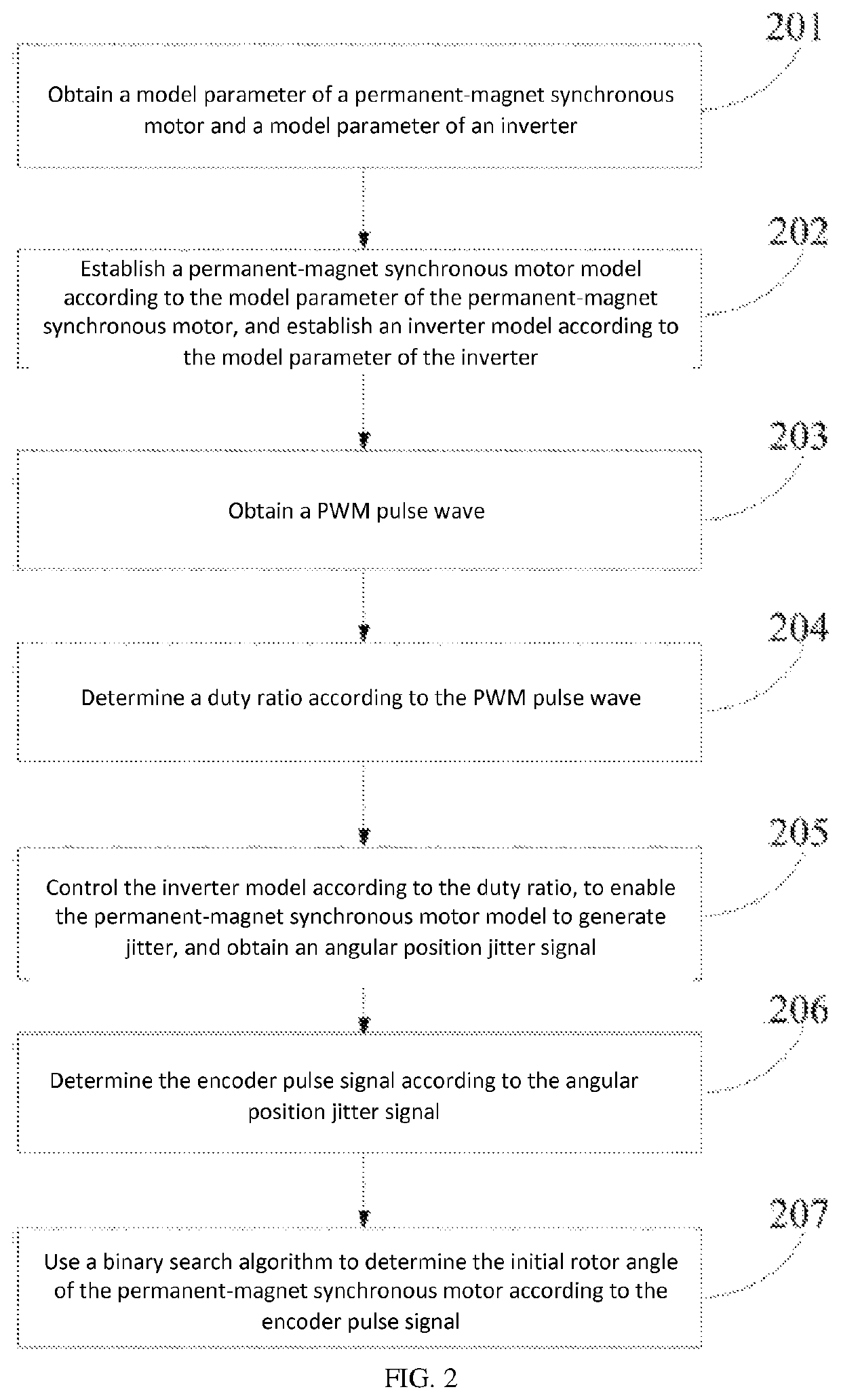
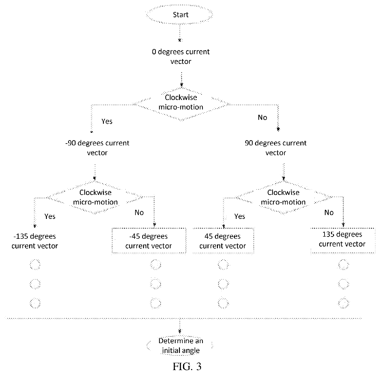
An initial rotor position detection device based on a permanent-magnet synchronous motor, including a host computer, a real-time simulation system, and a control system, where the real-time simulation system is connected to the control system, for determining an encoder pulse signal according to the model parameter of the permanent-magnet synchronous motor, the model parameter of the inverter, and a PWM pulse wave generated by the control system; and the control system is connected to the real-time simulation system, for using a binary search algorithm to determine an initial rotor angle of the permanent-magnet synchronous motor according to the encoder pulse signal sent by the real-time simulation system. A comprehensive closed-loop test circuit can be achieved by setting a host computer, a real-time simulation system, and a control system, and a used binary search algorithm can effectively and quickly detect an initial rotor position of a permanent-magnet synchronous motor.

Description

BACKGROUND OF INVENTION1. Field of Invention[0001]The present invention relates to the technical field of initial rotor position detection, and in particular, to an initial rotor position detection device and method based on a permanent-magnet synchronous motor.2. Background of Related Art[0002]A permanent-magnet synchronous motor features a simple structure, low loss, light weight, high efficiency, optimal reliability, and the like, and is often used in such occasions as electric vehicles and aerospace. When an initial rotor position is unknown, directly starting the permanent-magnet synchronous motor may lead to an expected phenomenon; therefore, in order to better control the permanent-magnet synchronous motor, the initial rotor position should be determined before starting the permanent-magnet synchronous motor.[0003]For high-power power electronic devices such as the permanent-magnet synchronous motor, experimenting directly on physical devices has many inconveniences. In the e...

Claims


Application Information

Patent Timeline
Patent Type & Authority Patents(United States)
IPC IPC(8): H02P21/32H02P6/34H02P21/22H02P6/20H02P21/34
CPCH02P21/32H02P6/34H02P6/20H02P21/34H02P21/22
Inventor DAI, YUXINGRUAN, XIUKAICAI, QIBOWU, KELU
Owner SHENZHEN JINGQUANHUA ELECTRONICS
Learn More