Method for operating blast furnace

a blast furnace and blast furnace technology, applied in vertical furnaces, furnaces, lighting and heating apparatuses, etc., can solve the problems of reducing combustion efficiency, deteriorating the contact property between oxygen and pulverized coal, increasing the temperature of the end of the lance, etc., and achieves high combustion calorie, advantageous in air permeability and heat balance of blast furnaces

Active Publication Date: 2019-11-26
JFE STEEL CORP
View PDF23 Cites 0 Cited by
  • Summary
  • Abstract
  • Description
  • Claims
  • Application Information

AI Technical Summary

Benefits of technology

[0007]The present invention was made in view of the problems as described above, and an object of the present invention is to provide a method for operating a blast furnace with which the combustion efficiency of a solid fuel, such as pulverized coal, is improved, thereby making it possible to improve productivity and reduce CO2 emissions.
[0011]In addition, the flammable gas used in the present invention is gas having combustibility higher than pulverized coal literally, and, in addition to hydrogen, city gas, LNG, and propane gas containing hydrogen as a main component, converter gas, blast furnace gas, coke-oven gas, and the like generated in a steel mill can be applied. Moreover, shale gas equivalent to LNG can also be used. The shale gas is natural gas obtained from a shale stratum, and is called an unconventional natural gas resource because of being produced in a place that is not a conventional gas field. Flammable gas, such as city gas, is ignited / combusted very rapidly, flammable gas having high hydrogen content has high combustion calorie, and furthermore, flammable gas is advantageous in air permeability and heat balance of a blast furnace because of not containing ash unlike pulverized coal.
[0012]In a method for operating a blast furnace of the present invention, a solid fuel and flammable gas are blown from an upstream lance configured by a double tube, and combustion-supporting gas is blown from a downstream lance on a downstream side in a hot air blast direction, so that oxygen used for combustion of the flammable gas is supplied from the downstream lance, and the solid fuel whose temperature has been increased by the combustion of the flammable gas is combusted along with the supplied oxygen. Therefore, the combustion efficiency of the solid fuel is improved, and accordingly, it makes possible to efficiently improve productivity and reduce CO2 emissions.

Problems solved by technology

However, as described in PTL 1, when the pulverized coal, LNG, and oxygen are blown from the triple tube lance, LNG is combusted ahead of the pulverized coal because LNG is easy to be combusted, as it is called, flammable, oxygen blown from the lance is used by the combustion of LNG, the contacting property between oxygen and the pulverized coal is deteriorated, and the combustion efficiency may be decreased.
Furthermore, since LNG is flammable and is rapidly combusted, when LNG is rapidly combusted at an end of the lance, the temperature of the end of the lance is increased, and wear damage, such as a crack and erosion, may be generated in the end of the lance.
When such wear damage is generated in the end of the lance, backfire, clogging of the lance, or the like may be induced.
In addition, as described in PTL 2, when the pulverized coal is blown from an end of the tuyere, and the pulverized coal is brought into contact with heat oxygen, the temperature increase of the pulverized coal is improved, but the pulverized coal is blown into a raceway quickly, and thus, there is no time for the pulverized coal to be combusted in the blast pipe and the tuyere, and the combustion efficiency of the pulverized coal may not be improved as the result.

Method used


Image

  • Method for operating blast furnace
  • Method for operating blast furnace
  • Method for operating blast furnace

Examples


Embodiment Construction

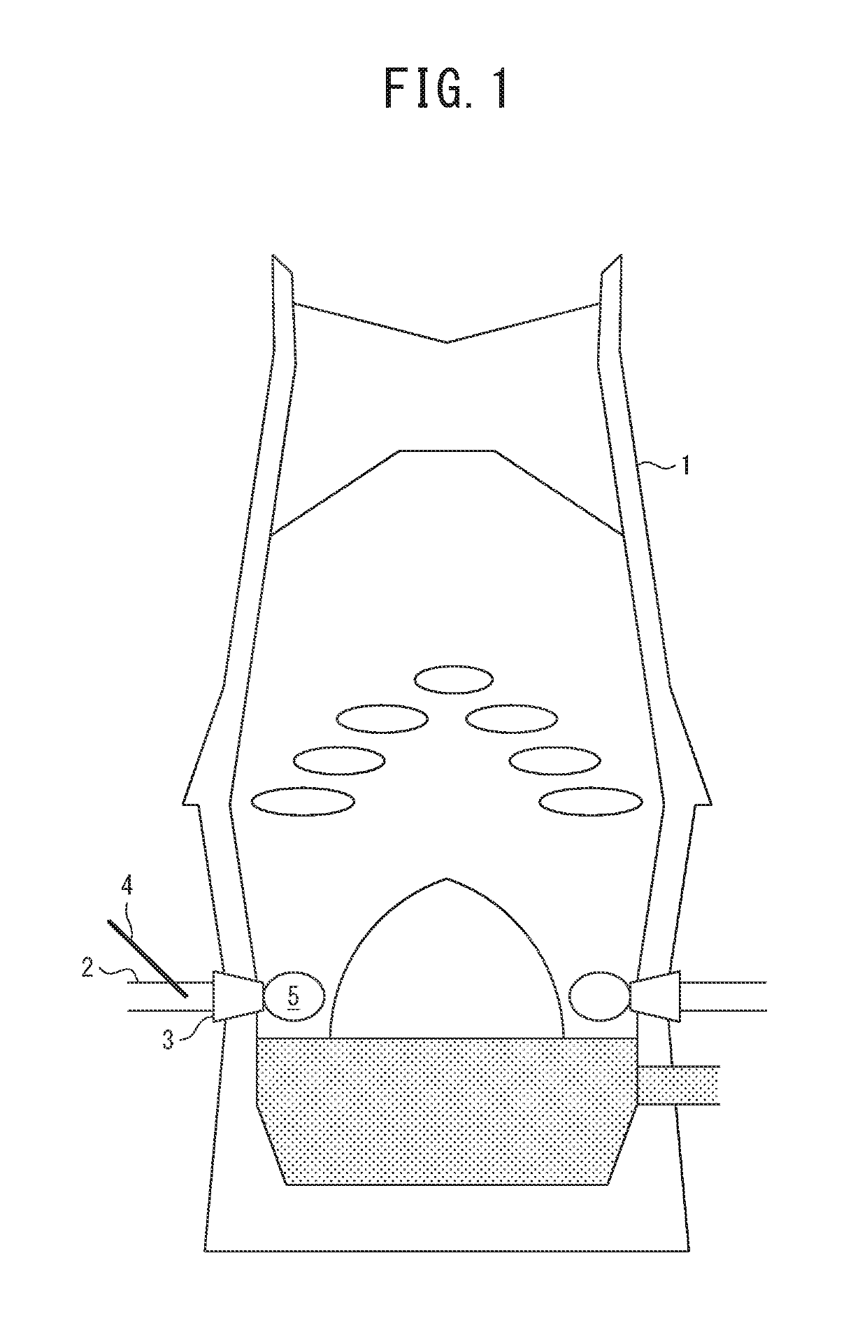
[0025]Next, one embodiment of a method for operating a blast furnace of the present invention will be described with reference to the drawings. FIG. 1 is an overall view of a blast furnace to which the method for operating a blast furnace of the present embodiment is applied. As illustrated in the drawing, a blast pipe 2 for blasting hot air is connected to a tuyere 3 of a blast furnace 1, and a lance 4 is arranged so as to penetrate the blast pipe 2. As the hot air, air is used. A combustion space called a raceway 5 exists at a coke deposit layer in front of the tuyere 3 in a hot air blast direction, and reduction of iron ore, that is, manufacture of pig iron is primarily performed in the combustion space. Although, in the drawing, only one lance 4 is inserted into the blast pipe 2 on the left side in the drawing, as is well known, the lance 4 can be set to be inserted into any of the blast pipe 2 and the tuyeres 3 circumferentially disposed along the furnace wall. In addition, the...


PUM

PropertyMeasurementUnit
circumferential direction angleaaaaaaaaaa
distanceaaaaaaaaaa
blowing speedaaaaaaaaaa

Abstract

To provide a method for operating a blast furnace with which the combustion efficiency of a solid fuel, such as pulverized coal, is improved, thereby making it possible to improve productivity and reduce CO2 emissions. Pulverized coal and LNG are blown from an upstream lance configured by a double tube, and oxygen is blown from a downstream lance on the downstream side in a hot air blast direction, so that oxygen used for preceding combustion of the LNG is supplied from the downstream lance, and the pulverized coal whose temperature has been increased by the combustion of the LNG is combusted along with the supplied oxygen. When a direction perpendicular to the hot air blast direction is designated as 0°, and a downstream direction and an upstream direction therefrom in the hot air blast direction are designated as positive and negative, respectively, a blowing direction of the oxygen from the downstream lance with respect to the blast direction ranges from −30° to +45°, and a blowing position of the oxygen from the downstream lance with reference to a position at which the upstream lance is inserted into a blast pipe ranges from 160° to 200° in terms of a blast pipe circumferential direction angle.

Description

CROSS REFERENCE TO RELATED APPLICATIONS[0001]This is the U.S. National Phase application of PCT / JP2016 / 000931, filed Feb. 22, 2016, which claims priority to Japanese Patent Application No. 2015-039968, filed Mar. 2, 2015, the disclosures of these applications being incorporated herein by reference in their entireties for all purposes.TECHNICAL FIELD OF THE INVENTION[0002]The present invention relates to a method for Operating a blast furnace with which the combustion temperature is increased by blowing pulverized coal from a tuyere of a blast furnace, thereby achieving an improvement of productivity and a reduction in CO2 emissions.BACKGROUND OF THE INVENTION[0003]In recent years, global warming due to an increase in carbon dioxide emissions has become a problem, and the controlling CO2 emissions is an important issue also in the steel industry. In response to this, the operation with a low reduction agent ratio (abbreviated as low RAR, total amount of a reducing agent blown from a ...

Claims


Application Information

Patent Timeline
Patent Type & Authority Patents(United States)
IPC IPC(8): C21B5/00C21B7/16F27B1/16C21B9/10F27B7/02
CPCF27B7/02C21B7/163C21B5/003C21B9/10F27B1/16C21B2005/005C21B5/00C21B5/001C21B7/16C21B7/00F27D7/02
Inventor YAMAMOTO, NAOKIMURAO, AKINORIKAWASHIMA, TOMOYUKIOOYAMA, NOBUYUKI
Owner JFE STEEL CORP
Why Eureka
Try Eureka