
Microcellular microstructure and method for manufacturing same

a micro-container and micro-cell technology, applied in the field of micro-container microstructure, can solve the problems of inability to easily use the system, inability to accurately understand the intracellular delivery mechanism through ultrasound technology, and inability to effectively administer drugs in lesions, etc., to achieve efficient loading and easy insertion

Active Publication Date: 2019-10-15
JUVIC INC
View PDF24 Cites 0 Cited by
  • Summary
  • Abstract
  • Description
  • Claims
  • Application Information

AI Technical Summary

Benefits of technology

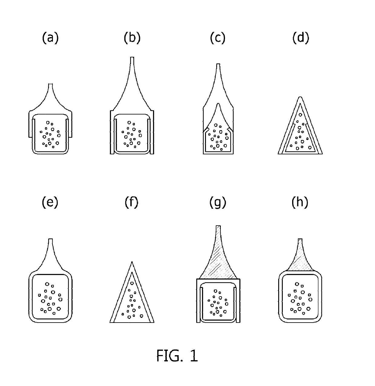
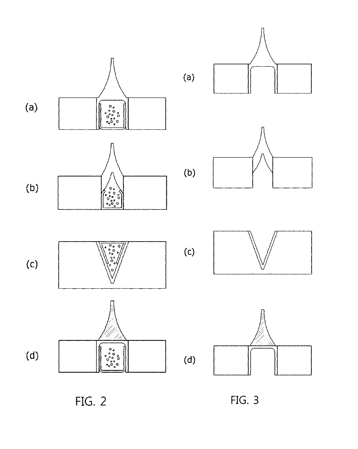
The present invention solves problems with existing methods of delivering drugs through the skin. The invention is a small container with a sharp tip that can be easily inserted into the body. The container can be filled with different types of drugs, ensuring efficacy and stability. When the container is pressed onto the skin, it can release the drug directly through the skin, eliminating side effects and ensuring accurate delivery. The invention is easy to use and can provide a more user-friendly experience compared to existing patch products. The load of drugs in the container can reach 100%, making it a more efficient delivery system.

Problems solved by technology

This system operates under a principle that a drug acts locally or systemically through the skin, but it has a limitation in delivery in that only small-molecular-weight compounds and very few hydrophobic drugs can pass through the skin barrier, and it is disadvantageous in that, even though passing through the skin barrier, the drug is not effective in a lesion while maintaining an appropriate amount thereof.
However, the electroporation system is inconvenient when used, and thus it is difficult for ordinary people to easily use this system.
However, since accurate understanding of the intracellular delivery mechanism through the ultrasound technology is still lacking, much research is needed to apply the ultrasound technology as a practical transdermal drug delivery technology.
However, unlike other transdermal drug delivery technologies, the jet injection technology has a problem in that a drug tends to spread widely rather than locally, and thus cannot be delivered intensively to the dermis, and shows skin side effects such as blisters, erythema, hardening, hematoma, and the like.
For efficient drug delivery, an adhesive patch needs to be attached to the skin for about 1 hour to about 2 hours, which is the point in time when the biodegradable polymer matrix is completely dissolved, resulting in side effects such as erythema, inflammation, allergic reactions, and the like.
Recent research shows that, when a biodegradable microneedle patch is applied to the skin, the microneedles do not completely penetrate into the skin, resulting in incomplete drug delivery efficiency (Ryan F. Donnelly et al.
Due to mixing of a polymer with a drug during fabrication of microneedles, the polymer and the drug interact with each other, resulting in a drastic decrease in activity of the drug.
However, a separate device designed for high-pressure dispensing is needed to percutaneously deliver a powder-type drug, a gas should be refilled after being dispensed once, and the particle size of a sprayable powered drug is limited.

Method used


Image

  • Microcellular microstructure and method for manufacturing same
  • Microcellular microstructure and method for manufacturing same
  • Microcellular microstructure and method for manufacturing same

Examples


example 1

Fabrication of Template for Substrate with Holes Formed Therein

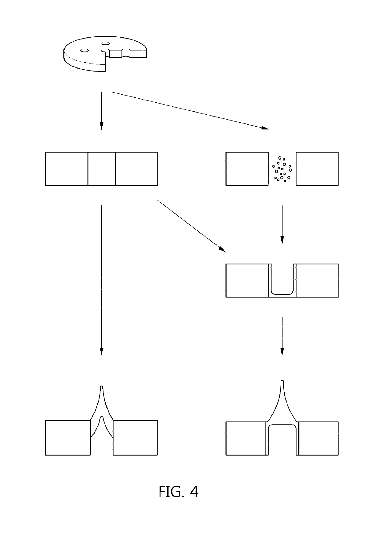
[0128]A template for a substrate with holes formed therein was fabricated using a molding method according to a micro electro mechanical systems (MEMS) process.

[0129]First, to fabricate the template for a substrate with holes formed therein, a circular template formed of steel use stainless (SUS) was fabricated using a laser cutting technology, and pillars having a diameter of 190 μm and a length of 770 μm were formed on a surface of the template (see FIG. 5(a)).

[0130]Subsequently, a polydimethylsiloxane (PDMS) solution was poured into the template and solidified, thereby completing the fabrication of a substrate with holes formed therein (see FIGS. 5(d) and 5(e)). FIG. 5(d) illustrates a cylindrical PDMS substrate with holes formed therein, and FIG. 5(e) illustrates a rectangular pillar-shaped PDMS substrate with holes formed therein.

example 2

Filling Substrate with Holes Formed Therein with Powder-type Sample

[0131]A substrate with cylindrical holes formed therein, formed of solidified PDMS, was coated with a powder-type calcein (fluorescent dye, Sigma-Aldrich) sample, vibrated, and then subjected to a cutting process, thereby completing the process of filling the holes with the sample.

[0132]The powder-type calcein sample was coated on surfaces of the holes, and then the vibrating process was performed using a vortex (Vortex-genie, Scientific Industries), and the cutting process was performed by cutting the surface of the film structure using an edge blade (DORCO).

[0133]FIG. 7(b) illustrates an image of an upper end portion of a substrate with holes formed therein, each of which has a diameter of 375 μm and a length of 843 μm, is completely filled with a powder-type calcein sample, and a cross-sectional image thereof. FIG. 7(c) illustrates an image of an upper end portion of a substrate with holes formed therein, each of ...

example 3

Molding of Microcontainer Film Structure in Substrate with Holes Formed Therein

[0134](1) A substrate with holes formed therein, each of which had a diameter of 500 μm and a length of 385 μm and a cylindrical shape, and was formed of PDMS, was filled with 10% w / v carboxymethylcellulose (CMC, low viscosity, Sigma-Aldrich) as a polymer composition sample, and then a solvent-removing process was performed twice, thereby molding a microcontainer film structure in the holes. A left-side image of FIG. 8(d) shows an upper end portion of the molding-completed microcontainer film structure, and a right-side image of FIG. 8(d) shows the microcontainer film structure separated from the substrate with holes formed therein. FIG. 8(e) illustrates a rectangular pillar-shaped microcontainer film structure separated from a PDMS mold for a substrate with rectangular pillar-shaped holes formed therein.

[0135](2) A substrate with holes formed therein, each of which had a diameter of 258 μm and a length o...


PUM

PropertyMeasurementUnit
volumeaaaaaaaaaa
volumeaaaaaaaaaa
volumeaaaaaaaaaa

Abstract

The present invention relates to a microcontainer microstructure including a microcontainer film structure having a sharp tip portion and a method of manufacturing the same.

Description

CROSS-REFERENCE TO RELATED APPLICATIONS[0001]This application is a national phase application under 35 U.S.C. § 371 of International Application No. PCT / KR2015 / 013826, filed Dec. 16, 2015, which claims priority to Korean Patent Application No. 10-2014-0181796, filed Dec. 16, 2014. The contents of the referenced applications are incorporated into the present application by reference.TECHNICAL FIELD[0002]The present invention relates to a microcontainer microstructure and a method of manufacturing the same.BACKGROUND ART[0003]A transdermal drug delivery system is a type of drug delivery system that delivers drugs through the skin, and is characterized by long duration and its ability to contain a large amount of drugs compared to other drug delivery systems such as oral administration agents, inhalants, injections, and the like. A first-generation transdermal drug delivery system is a patch-type product including a smoking cessation patch (nicotine patch), an inflammation treatment pa...

Claims


Application Information

Patent Timeline
Patent Type & Authority Patents(United States)
IPC IPC(8): A61K9/00A61K9/50A61M37/00A61M31/00
CPCA61K9/4841A61M37/0015A61M2037/003A61M2037/0046A61K9/0021A61M31/002A61M2037/0053A61P17/00A61K9/0024A61K9/4808A61K9/4833A61K9/4866A61M37/00A61M2037/0007A61K9/5005A61K9/5089
Inventor JUNG, HYUNG ILKIM, SU YONGYANG, HUI SUK
Owner JUVIC INC
Learn More