
Gamma ray detector with two-dimensional directionality

a detector and directionality technology, applied in the field of gamma ray detectors, can solve the problems of insufficient large inspection items such as trucks and railcars, difficult detection using current detector technology, and immediate worldwide threat of clandestine nuclear weapons, and achieve the effect of high detection efficiency, high angular precision, and maximum detection area

Inactive Publication Date: 2019-09-03
NEWMAN DAVID EDWARD
View PDF36 Cites 0 Cited by
  • Summary
  • Abstract
  • Description
  • Claims
  • Application Information

AI Technical Summary

Benefits of technology

The system enables rapid and accurate localization of gamma ray sources, reducing inspection times and improving sensitivity, while being lightweight, cost-effective, and suitable for various applications including cargo and personnel scanning.

Problems solved by technology

Clandestine nuclear weapons are an immediate worldwide threat.
Although nuclear and radiological threat materials emit gamma rays, heavy shielding greatly attenuates the signal; consequently they are difficult to detect using current detector technology.
This is insufficient for large inspection items such as trucks and railcars and shipping containers that extend in both the horizontal and vertical directions.
For these and many other inspection challenges, a one-dimensional localization is not enough.
Of course a pair of such prior-art detectors could be used to separately scan horizontally and vertically, but this would require two separate systems and would entail some kind of cumbersome coordination between them.
Also the two systems would each have its own background rate, further diluting the threat signature and requiring longer scan times. Alternatively, a single prior-art directional detector could scan horizontally first, then roll by 90 degrees, and then scan vertically; but this would take twice as long and would require a complicated mechanical joint.
Gamma cameras typically employ a collimator (pin-hole, multi-aperture, coded-aperture, or other type collimator), which inevitably results in a large, heavy, expensive system yet has low detection efficiency due to losses in the collimator.
In either case, the prior-art systems provide only a very approximate source direction at best, yet are even larger and more complex and less efficient than the collimated gamma cameras.

Method used


Image

  • Gamma ray detector with two-dimensional directionality
  • Gamma ray detector with two-dimensional directionality
  • Gamma ray detector with two-dimensional directionality

Examples


first embodiment

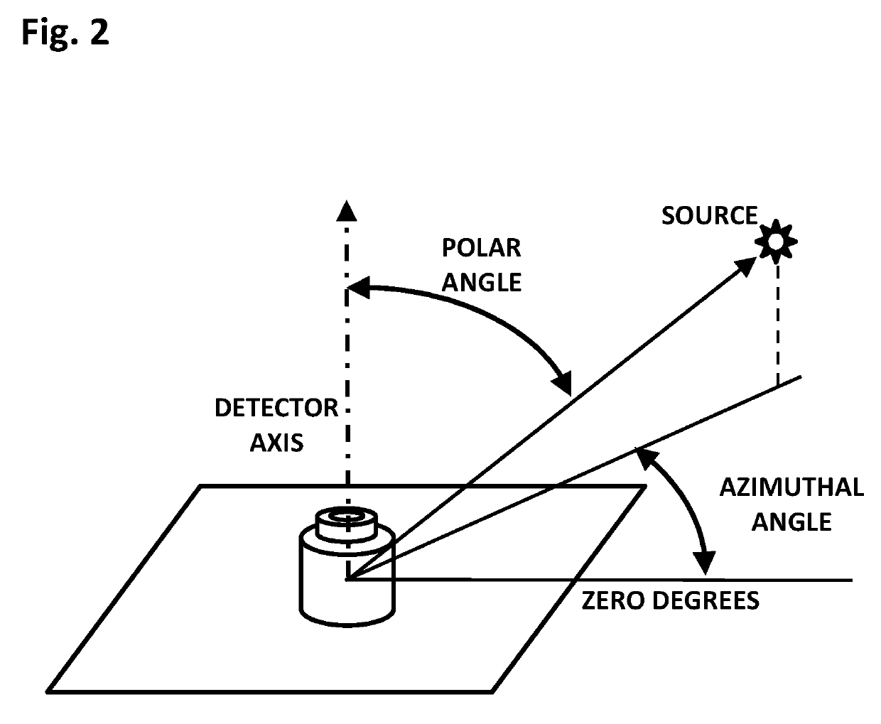
[0061]the invention comprises a hand-held survey meter, without a central detector. The meter includes a display showing the calculated azimuthal angle of the source, and other data. Operation of the instrument is very simple; the operator rotates the instrument manually, up or down or laterally, according to the indicated azimuthal angle, and thereby converges on the source. The polar angle is not determined and is not necessary in this case, since the operator can find the source simply by following the indicated direction. Normally the operator rotates the instrument slowly, so that it can update the calculated azimuthal angle in real time. If the operator rotates the detector too quickly, the detector axis will likely overshoot the source location; however the system will soon recalculate the azimuthal angle and update the display correctly to point back toward the source. Thus the invention is quite tolerant of operator behavior, quickly and gracefully recovering from overshoot...

second embodiment

[0062]A second embodiment comprises a hand-held survey meter which includes means for determining the detector orientation relative to the ground, such as a multi-axis accelerometer and an electronic compass. In that case, the detector orientation is known, and the polar angle is determined by interpolation between two sets of measurements at different detector orientations. Preferably the two orientations straddle the source; however if the two measurements are both on the same side of the source, a rough estimate of the polar angle can still be obtained by projection.

third embodiment

[0063]the invention comprises a hand-held meter or a fixed-site detector, in which a central detector is mounted in the shield. The central detector is configured to have a directional dependence that is quite different from the scintillator array, due to the central detector being in an axially centered position. By analyzing the scintillator signals and the central detector signals together, the polar angle can be calculated at each detector orientation, that is, without the need for correlating successive measurements at different orientations. For example, a ratio Rsc may be calculated, comprising the maximum scintillator counting rate divided by the central detector counting rate. Or, more preferably, the numerator (Rs) equals the maximum differential plus one-half the second-highest differential observed in the scintillator array, while the denominator (Rc) is the central detector counting rate. When calculated with this simple formula, the ratio Rsc=Rs / Rc is closely correlate...


PUM

PropertyMeasurementUnit
azimuthal angleaaaaaaaaaa
angleaaaaaaaaaa
signal contrastaaaaaaaaaa

Abstract

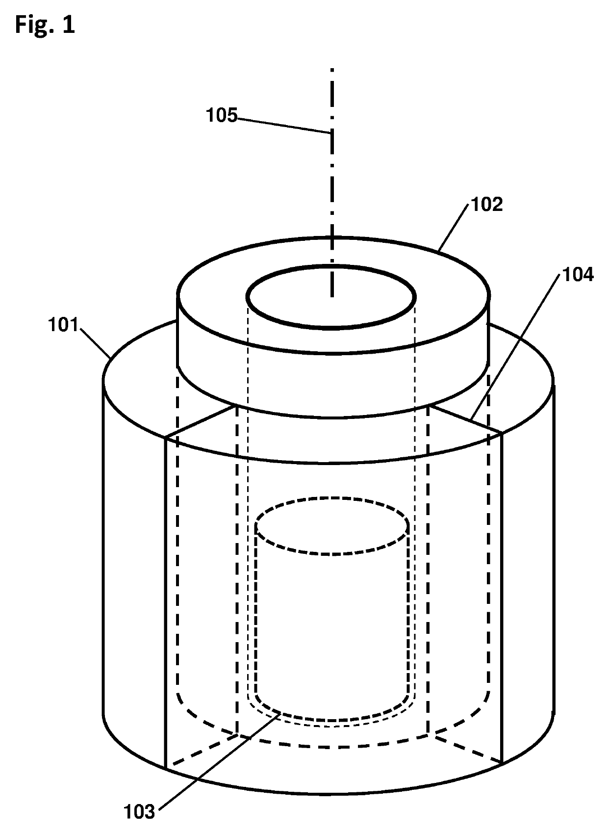
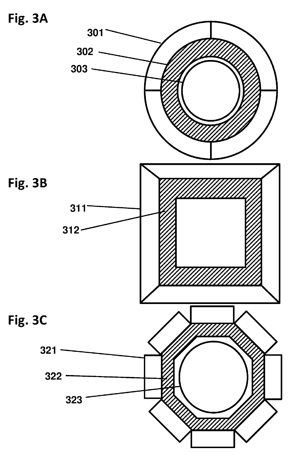
The invention is a gamma ray detector that locates a source, both horizontally and vertically. The detector comprises a tubular shield surrounded by scintillator panels. Gammas incident from one side can fully strike the scintillator facing the source, but are blocked from reaching the scintillators on the opposite side of the shield. The scintillator counting rates thus indicate the lateral direction of the source. By iteratively rotating toward the highest-counting scintillator, the detector converges to the source. An additional, central detector can be mounted within the tubular shield. When analyzed with the outer scintillators, the central detector determines the overall angular separation between the source and the detector axis, thereby locating the source in two dimensions automatically. The invention enables rapid detection and precise localization of clandestine nuclear and radiological weapons, despite shielding and clutter obfuscation, while quickly passing clean loads.

Description

CROSS REFERENCES TO RELATED APPLICATIONS[0001]This application is a continuation of U.S. patent application Ser. No. 15 / 807,556 entitled “Gamma Ray Detector with Two-Dimensional Directionality” and filed on Nov. 8, 2017 which claims the benefit of U.S. Provisional Patent Application No. 62 / 500,474 entitled “Directional Radiation Detector” and filed on May 2, 2017, and U.S. Provisional Patent Application No. 62 / 569,581 entitled “Gamma Ray Detector with Two-Dimensional Directionality” and filed on Oct. 8, 2017, and U.S. Provisional Patent Application No. 62 / 580,960 entitled “Gamma Ray Detector with Two-Dimensional Directionality” and filed on Nov. 2, 2017, the entire disclosures of which are incorporated herein by reference.FIELD OF INVENTION[0002]The invention relates to gamma ray detectors that indicate the direction of a radiation source, and particularly to those that indicate the source direction in two dimensions.BACKGROUND OF THE INVENTION[0003]Clandestine nuclear weapons are a...

Claims


Application Information

Patent Timeline
Patent Type & Authority Patents(United States)
IPC IPC(8): G01T1/29G01V5/00G01T3/06G01N23/04G01T1/20G01T1/167
CPCG01T1/167G01T1/2907G01T1/20G01T3/065G01V5/0016G01N23/04G01V5/0091G01V5/22G01V5/281
Inventor NEWMAN, DAVID EDWARD
Owner NEWMAN DAVID EDWARD
Learn More