
Systems, device, and methods for joint fusion

a joint fusion and system technology, applied in the field of systems, devices and methods for joint fusion, can solve the problems of affecting the ability of each spinal segment to bear weight, too much movement between two vertebrae, and localized pain and difficulties

Active Publication Date: 2019-07-30
SI BONE INC
View PDF656 Cites 20 Cited by
  • Summary
  • Abstract
  • Description
  • Claims
  • Application Information

AI Technical Summary

Benefits of technology

This patent describes a method for fusing and stabilizing adjacent bones in the lumbar spine. The method involves using elongated, stem-like implant structures made of materials like bone morphogenetic proteins, hydroxyapatite, and steroids. These structures are designed to promote bony in-growth onto or through the implant, which accelerates the fusion process. The method is minimally invasive and can be performed on adults or children. It offers a safe and effective way to stabilize spinal segments and treat degenerative spular disorders.

Problems solved by technology

Degenerative changes in the spine can adversely affect the ability of each spinal segment to bear weight, accommodate movement, and provide support.
When one segment deteriorates to the point of instability, it can lead to localized pain and difficulties.
Segmental instability allows too much movement between two vertebrae.
The excess movement of the vertebrae can cause pinching or irritation of nerve roots.
It can also cause too much pressure on the facet joints, leading to inflammation.
It can cause muscle spasms as the paraspinal muscles try to stop the spinal segment from moving too much.
The instability eventually results in faster degeneration in this area of the spine.
Degenerative changes in the spine can also lead to spondylolysis and spondylolisthesis.
An untreated persistent, episodic, severely disabling back pain problem can easily ruin the active life of a patient.
However, in for severe and persistent problems that cannot be managed by these treatment options, degenerative changes in the spine may require a bone fusion surgery to stop both the associated disc and facet joint problems.
In some cases the vertebrae are moved back to the normal position prior to performing the fusion, and in others the vertebrae are fused where they are after the slip, due to the increased risk of injury to the nerve with moving the vertebra back to the normal position.
Like all invasive open surgical procedures, such operations on the spine risk infections and require hospitalization.
Invasive open surgical techniques involving the spine continue to be a challenging and difficult area.

Method used


Image

  • Systems, device, and methods for joint fusion
  • Systems, device, and methods for joint fusion
  • Systems, device, and methods for joint fusion

Examples


Embodiment Construction

[0244]Tissue Dilator and Protector

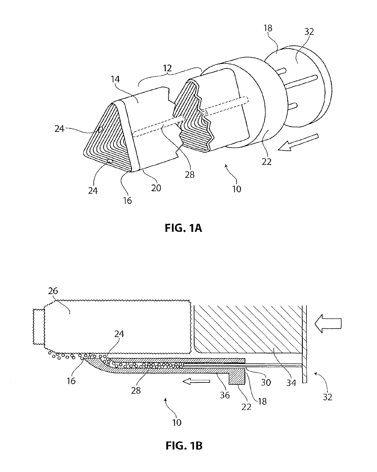
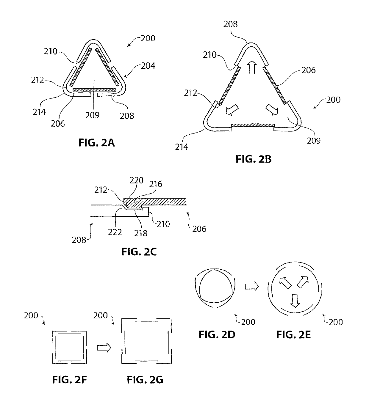
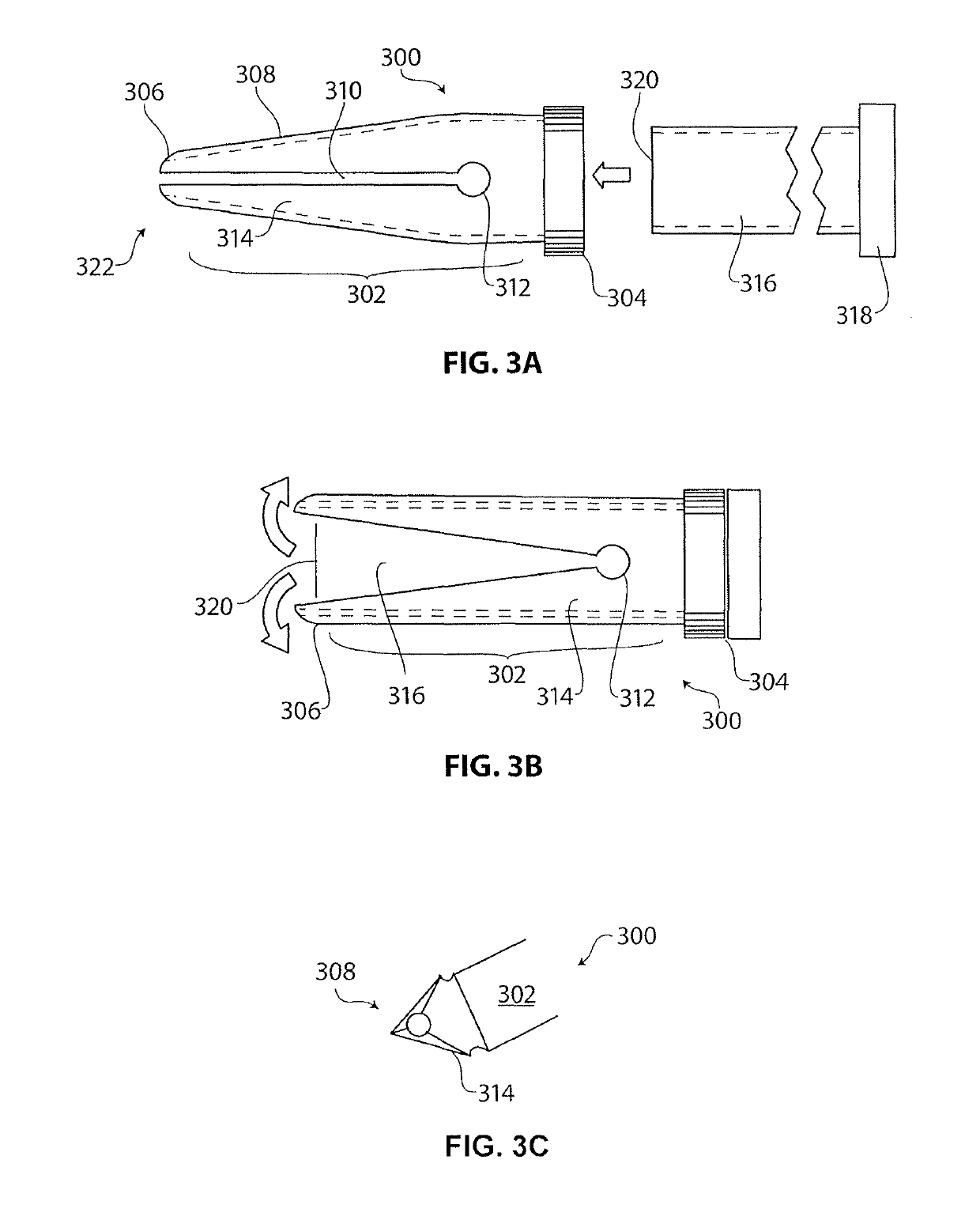
[0245]FIGS. 1A and 1B are a perspective view and a longitudinal cross-sectional view, respectively, of an embodiment of a dilator 10 with an integrated infusion system. In some embodiments, the dilator 10 can be used as a soft tissue protector in addition to or in place of its function as a dilator 10. In some embodiments, the dilator 10 has a longitudinal body 12 with a wall 14 that can be shaped to match the cross-sectional profile of an implant 26. The wall 14 can define a passage that extends through the longitudinal body. For example, if the implant 26 has a triangular cross-section, then the hollow interior of the dilator 10 can have a triangular cross-section that matches the implant geometry, such that the implant 26 can pass through the interior of the dilator 10. In other embodiments, the implant 26 can have other cross-sectional geometries, such as a square implant, a hexagonal implant and the like, and the cross-sectional shape of the in...


PUM


Abstract

The present invention relates generally to implants and tools for the fixation or fusion of joints or bone segments. These tools include tissue dilators and protectors. Other tools include broaches used to shape bores in bone. The tools can also include a system for removing an implant from bone. Implants can include assemblies of one or more implant structures that make possible the achievement of diverse interventions involving the fusion and / or stabilization of lumbar and sacral vertebra in a non-invasive manner, with minimal incision, and without the necessitating the removing the intervertebral disc. Implants for fusing both sacroiliac joints of a patient include a long implant that extends across both sacroiliac joints.

Description

CROSS REFERENCE TO RELATED APPLICATIONS[0001]This application is a continuation-in-part of U.S. patent application Ser. No. 13 / 794,542, filed Mar. 11, 2013, titled “TISSUE DILATOR AND PROTECTOR,” now U.S. Patent Application Publication No. 2013 / 0267989, which claims priority to U.S. Provisional Patent Application No. 61 / 609,043, filed Mar. 9, 2012, titled “TISSUE DILATOR AND PROTECTOR,” which is hereby incorporated by reference in its entirety.[0002]This application also is a continuation-in-part of U.S. patent application Ser. No. 14 / 216,790, filed Mar. 17, 2014, titled “SYSTEMS AND METHODS FOR IMPLANTING BONE GRAFT AND IMPLANT,” now U.S. Patent Application Publication No. 2014 / 0276846, which claims priority to U.S. Patent Provisional Application No. 61 / 793,357, filed Mar. 15, 2013, and titled “SYSTEMS AND METHODS FOR IMPLANTING BONE GRAFT AND IMPLANT,” which is herein incorporated by reference in its entirety.[0003]This application also is a continuation-in-part of U.S. patent app...

Claims


Application Information

Patent Timeline
Patent Type & Authority Patents(United States)
IPC IPC(8): A61F2/30A61F2/46A61B17/84A61B17/16A61B17/88A61B17/34A61B17/02A61F2/44A61B17/00
CPCA61F2/30988A61B17/1642A61B17/1671A61B17/3439A61B17/84A61B17/88A61B17/8872A61F2/4455A61F2/4611A61B17/0218A61F2002/30995A61B2017/00526A61B2017/3433A61F2002/3092A61F2002/3093A61F2002/30156A61B17/1604A61B17/1659A61B17/1664A61B17/68A61B17/7055A61B17/7064A61B17/7065A61B17/7097A61B17/846A61B17/92
Inventor MAULDIN, RICHARD G.RASHBAUM, RALPH F.REILEY, MARK A.YERBY, SCOTT A.SAND, PAULSCHNEIDER, BRET W.RODRIGUEZ, JOSEDOMINGO, NICANORLEUNG, JOANNE
Owner SI BONE INC
Learn More