LED package
a technology of led packages and led elements, applied in the field of led packages, can solve the problems of difficult to reduce the size and height of led packages, and the efficiency of extracting light from led elements will conversely decrease, so as to increase the light extraction efficiency and reduce the height and size of led packages
- Summary
- Abstract
- Description
- Claims
- Application Information
AI Technical Summary
Benefits of technology
Problems solved by technology
Method used
Image
Examples
first embodiment
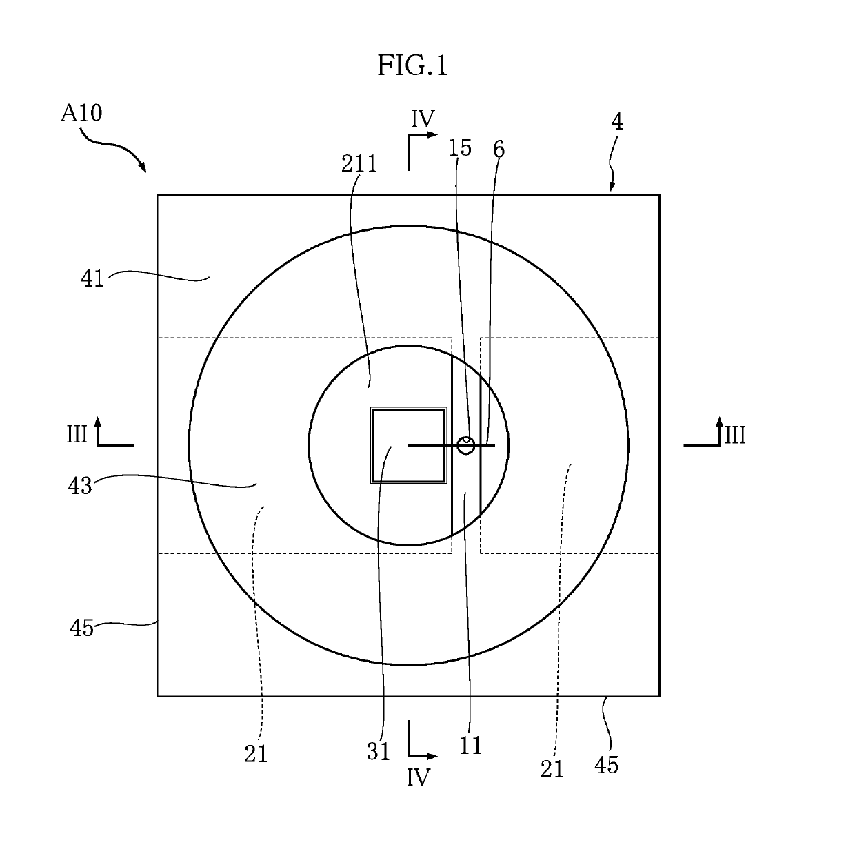
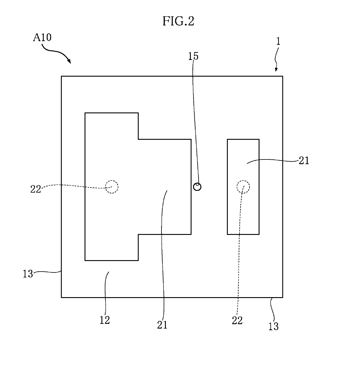
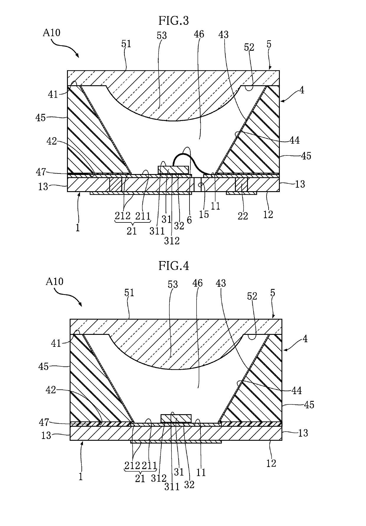
[0051]An LED package A10 according to a first embodiment of the present invention will be described with reference to FIGS. 1 to 5. The LED package A10 shown in these figures is surface-mounted on the circuit board of a remote sensor, for example. The LED package A10 according to this embodiment is provided with a base board or substrate 1, conductive parts 21, a communication conductive part 22, an LED element 31, a junction layer 32, a case 4, a lid 5 and a bonding wire 6. The LED package A10 is rectangular in plan view.
[0052]FIG. 1 is a plan view of the LED package A10, and the lid 5 is omitted for convenience of understanding. FIG. 2 is a bottom view of the LED package A10. FIG. 3 is a cross-sectional view taken along a line III-III in FIG. 1. FIG. 4 is a cross-sectional view taken along a line IV-IV in FIG. 1. FIG. 5 is a perspective view of the lid 5 of the LED package A10. Note that in FIGS. 3 and 4, the lid 5 is illustrated and not omitted.
[0053]The board 1 is for supporting...
first modified example of first embodiment
[0079]An LED package A11 according to a first modified example of the first embodiment of the present invention will be described with reference to FIG. 6. FIG. 6 is a cross-sectional view of the LED package A11, and the cross-sectional position thereof is the same as in FIG. 3.
[0080]The LED package A11 of this modified example is provided with sealing resin 7 in contrast to the above-described LED package A10. The sealing resin 7 is a synthetic resin that covers the LED element 31 and allows light to pass therethrough, and in this modified example, is composed of silicone resin. The sealing resin 7 may be a synthetic resin containing a phosphor and configured to allow light to pass therethrough, and more specifically, may also be silicone resin containing a phosphor. For example, if the LED element 31 emits blue light, white light is emitted from the LED package A11 by using the sealing resin 7 containing a yellow-color phosphor. If the LED element 31 emits purple near-ultraviolet ...
second modified example of first embodiment
[0082]An LED package A12 according to a second modified example of the first embodiment of the present invention will be described with reference to FIG. 7. FIG. 7 is a cross-sectional view of the LED package A12, and the cross-sectional position thereof is the same as in FIG. 3.
[0083]The LED package A12 of this modified example is provided with the sealing resin 7 in contrast to the above-described LED package A10. In this modified example, the material of the sealing resin 7 is the same as that in the LED package A11. Therefore, the sealing resin 7 may be a synthetic resin containing a phosphor and configured to allow light to pass therethrough, similarly to the LED package A11. In this modified example, the entirety of the through area 46 is filled with the sealing resin 7. Note that the board 1 of the LED package A12 does not have the ventilation hole 15 formed therein, unlike the LED package A10.
[0084]According to this modified example, it is also possible to increase the light...
PUM
 Abstract
Description
Claims
Application Information
 - R&D
- Intellectual Property
- Life Sciences
- Materials
- Tech Scout
- Unparalleled Data Quality
- Higher Quality Content
- 60% Fewer Hallucinations
Browse by: Latest US Patents, China's latest patents, Technical Efficacy Thesaurus, Application Domain, Technology Topic, Popular Technical Reports.
© 2025 PatSnap. All rights reserved.Legal|Privacy policy|Modern Slavery Act Transparency Statement|Sitemap|About US| Contact US: help@patsnap.com


