
Towers for substrate carriers

a technology of substrate carriers and towers, which is applied in the direction of basic electric elements, semiconductor/solid-state device manufacturing, electrical equipment, etc., can solve the problems of system failure to address the intrusion of ambient air into the substrate container, adversely affecting the product yield of the resident wafer, and adversely affecting the yield of the resident substrates. achieve the effect of improving purging performan

Active Publication Date: 2019-07-09
ENTEGRIS INC
View PDF26 Cites 5 Cited by
  • Summary
  • Abstract
  • Description
  • Claims
  • Application Information

AI Technical Summary

Benefits of technology

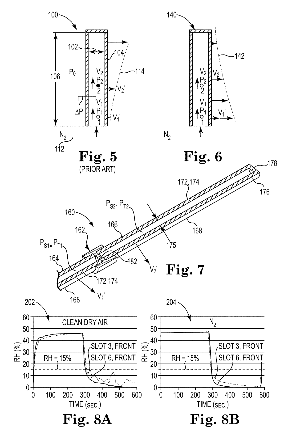
The patent text describes a porous tower diffuser assembly that can be added to front opening wafer containers for better purge performance. The assembly includes a fitting with an offset portion and a diffuser tower connected to the fitting. The diffuser tower tube has a flared fitting that extends over the upwardly facing nipple. The assembly helps to sweep the floor of the container and counter the inrush of ambient air. Various embodiments also explain how the assembly can effectively purge the high flow of air entering the container at the lower wafer slots. In summary, the patent text describes a way to improve the purge performance of wafer containers by purging the air that enters at the lower slots.

Problems solved by technology

During insertion or removal of substrates from a substrate container, such as front opening wafer containers, traces of dust, gaseous impurities, or increased humidity can be introduced into the substrate container, adversely affecting product yield of the resident wafers.
These systems do not address the intrusion of ambient air into the substrate container during insertion or removal of substrates, i.e., when the access door is removed and the opening is exposed.
Such intrusion of ambient air can adversely affect the yield of the resident substrates, even when the ambient environment is that of a clean room.
Additionally, these references do not address the connections between a diffuser tube and an upwardly facing fitting of a purge port assembly.

Method used


Image

  • Towers for substrate carriers
  • Towers for substrate carriers
  • Towers for substrate carriers

Examples


Embodiment Construction

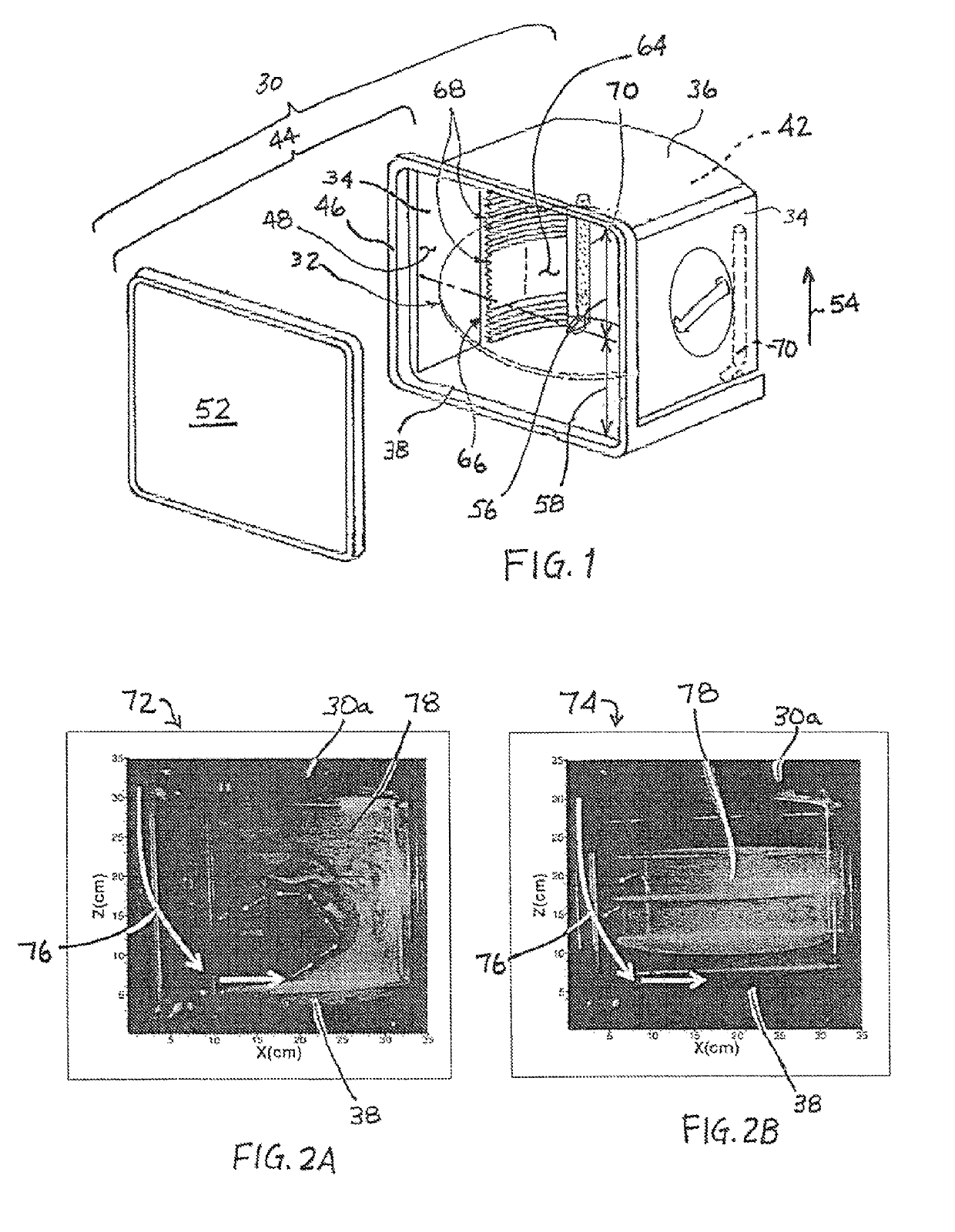
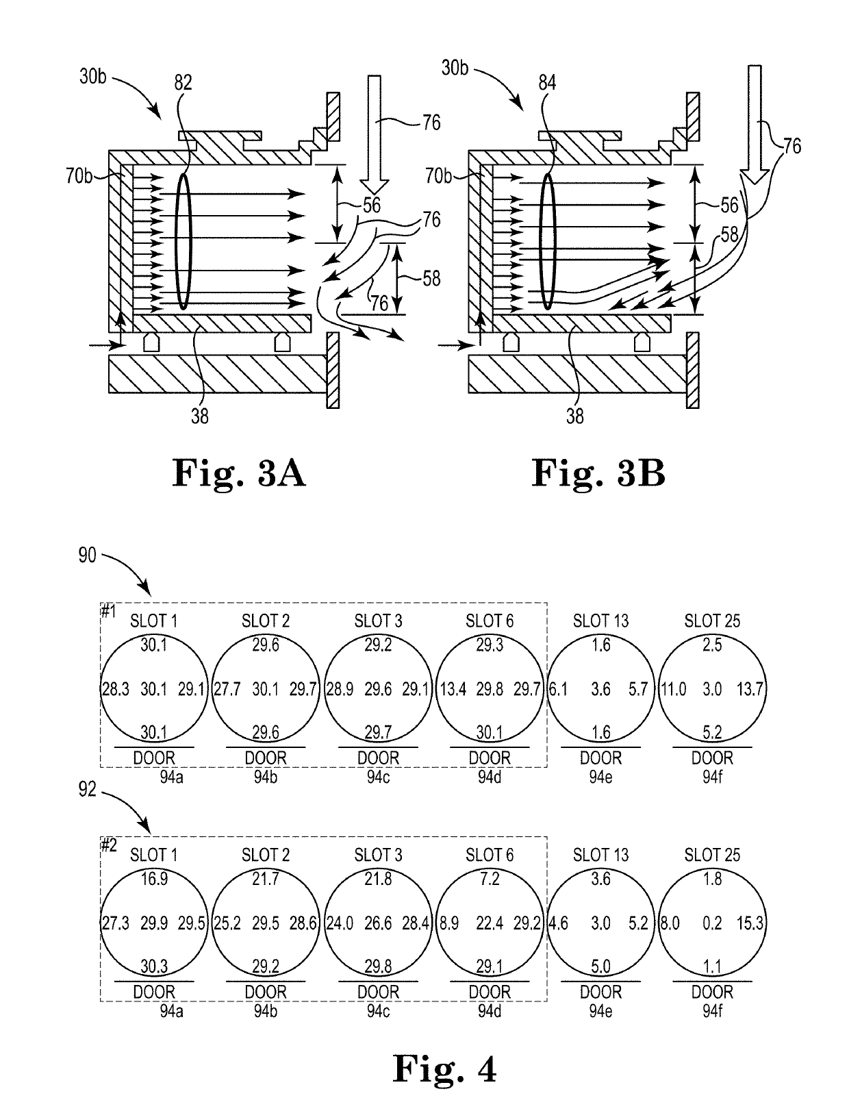
[0007]Various embodiments of the disclosure generate an uneven flow distribution that provides a non-uniform flow distribution at the opening. The flow distribution at the opening is tailored to counter the inrush of ambient air that would otherwise occur. In one embodiment, where the opening defines a plane that is in a substantially vertical orientation, the non-uniform flow distribution is tailored to deliver a greater flow rate to the bottom half of the opening than to the top of the opening. Implementing the flow rates and velocity profiles disclosed herein has been demonstrated to maintain the relative humidity within the substrate container substantially below a target value of 15%, even when the door to the substrate container is unsealed and removed from the opening.

[0008]Structurally, in one embodiment, a system for transporting substrates is disclosed, comprising a substrate container including an opening for insertion / removal of substrates and a door adapted to sealably ...


PUM


Abstract

A diffuser tower assembly having a diffuser with a flared end and a fitting with an offset portion and nipple sized for the flared end. The assembly may be configured for providing low coverage purging. Diffuser tower assemblies may be in the form of a kit for retrofitting existing front opening wafer containers. The inlet fitting may include structure that enhances purge characteristics near the base of the porous media diffuser for enhanced sweeping of the floor of the substrate container. Embodiments of the disclosure generate an uneven flow distribution that provides a non-uniform flow distribution at the opening. In an embodiment, where the opening is in a substantially vertical orientation, the non-uniform flow distribution is tailored to deliver a greater flow rate to the bottom half of the opening than to the top of the opening.

Description

RELATED APPLICATIONS[0001]This present application is a National Phase entry of PCT Application No. PCT / US2014 / 060533, filed Oct. 14, 2014, which claims the benefit of U.S. Provisional Patent Application No. 61 / 890,611, filed Oct. 14, 201 and U.S. Provisional Patent Application No. 61 / 940,744, filed Feb. 17, 2014, the disclosures of which are incorporated by reference herein in their entireties.TECHNICAL FIELD OF THE DISCLOSURE[0002]The present disclosure relates to transportable substrate containers suitable for use in storing or transporting objects such as semiconductor wafers in a clean environment and more particularly to systems and methods for purging the environment within said container during exposure of the container to the ambient environment.BACKGROUND OF THE DISCLOSURE[0003]During insertion or removal of substrates from a substrate container, such as front opening wafer containers, traces of dust, gaseous impurities, or increased humidity can be introduced into the sub...

Claims


Application Information

Patent Timeline
Patent Type & Authority Patents(United States)
IPC IPC(8): H01L21/673
CPCH01L21/67393H01L21/67051H01L21/67376H01L21/67379H01L21/67386
Inventor SMITH, MARK V.BEATTY, CHRISTOPHERBANDREDDI, MURALI
Owner ENTEGRIS INC
Learn More