
Device for sweeping continuous slab band edge part

A continuous plate and belt edge technology, which is applied in the direction of drying solid materials, chemical instruments and methods, and drying solid materials without heating, can solve the problems of low utilization rate of compressed air, poor purging effect, and air dispersion, etc. High efficiency, good blowing effect and accurate blowing position

Inactive Publication Date: 2009-05-20
WISDRI ENG & RES INC LTD
View PDF0 Cites 4 Cited by
  • Summary
  • Abstract
  • Description
  • Claims
  • Application Information

AI Technical Summary

Problems solved by technology

[0002] It turns out that this kind of equipment uses multiple sets of nozzles fixed at different positions to blow the edges of continuous strips (strips) of different widths. When the width of the continuous strip changes, the operator opens the nozzle group at the corresponding width position. The disadvantages of the air inlet valve are: 1) In order to compensate for the deviation of the strip, the nozzle needs to have a wide injection range, resulting in scattered air flow, low utilization rate of compressed air, high energy consumption, and poor blowing effect; 2) each time When the width of the produced plate changes, manual operation is required

Method used


Image

  • Device for sweeping continuous slab band edge part
  • Device for sweeping continuous slab band edge part
  • Device for sweeping continuous slab band edge part

Examples


Embodiment Construction

[0019] Further describe the present invention below in conjunction with accompanying drawing:

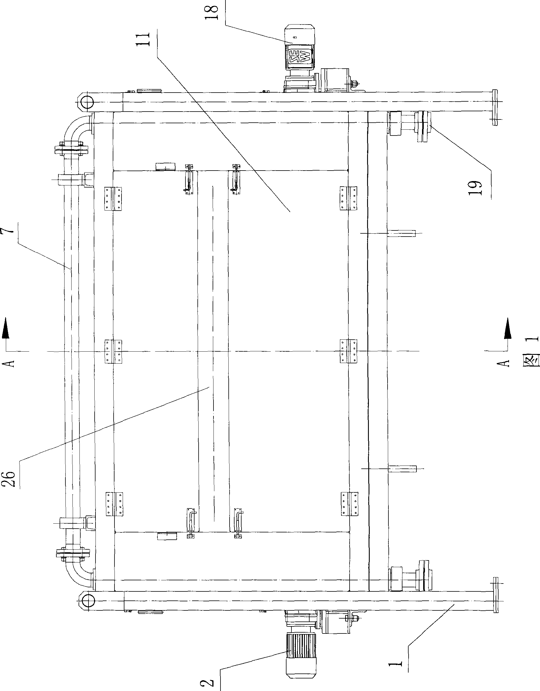
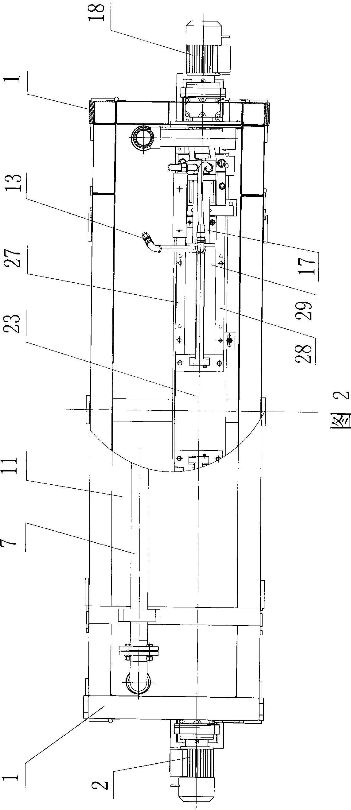
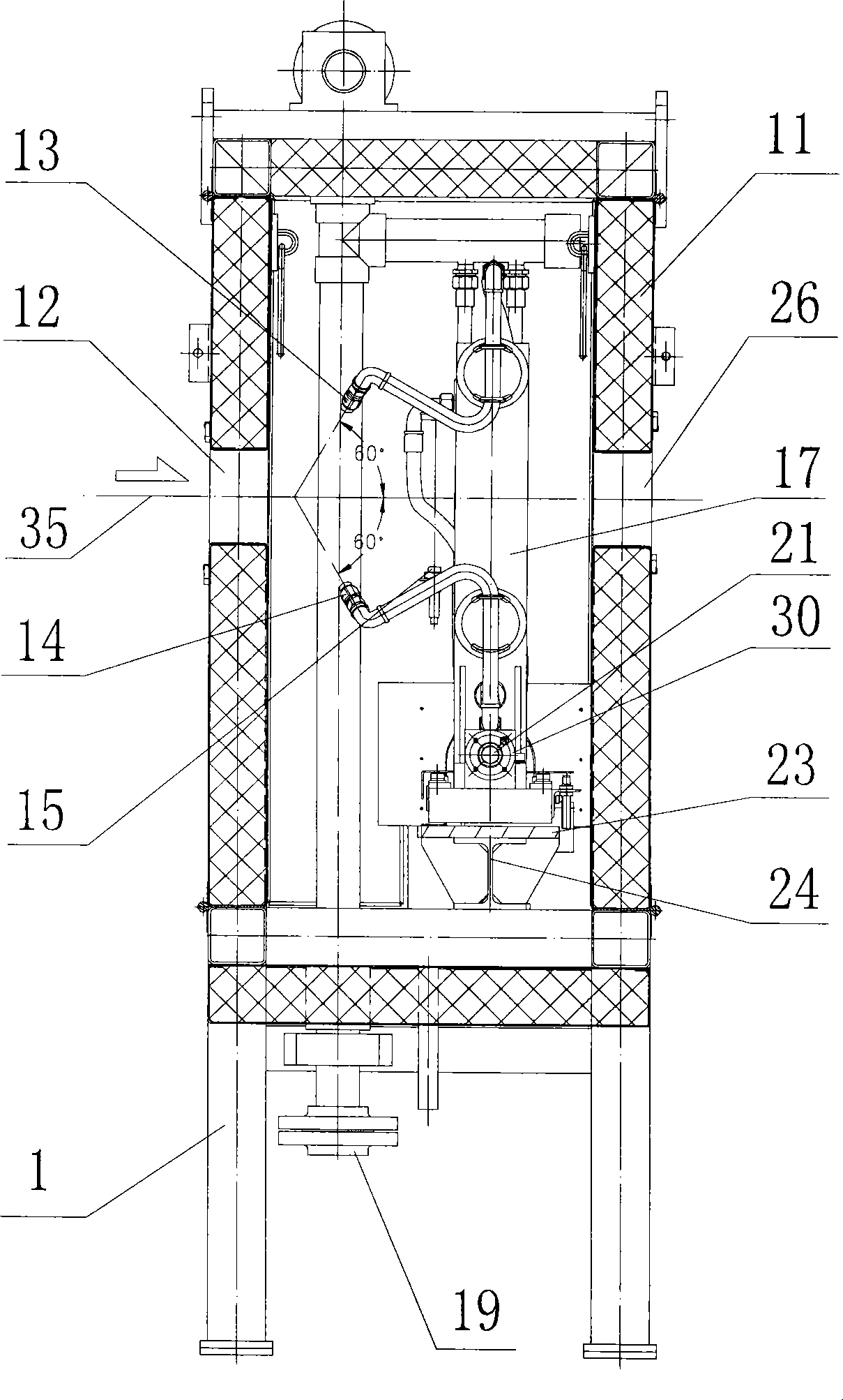
[0020] As shown in Figure 1, the blowing device for the edge of the continuous strip includes a body, a left width adjustment device, a right width adjustment device, a compressed air main pipe 7, an upper left nozzle 8, a lower left nozzle 9, an upper right nozzle 13, and a lower right nozzle 15 There is a purge cavity 10 in the body; the rear side of the body has a strip inlet 12, and the front side of the body has a strip outlet 26, and the strip inlet 12 and the strip outlet 26 communicate with the purge cavity 10 respectively;

[0021] The body includes a frame 1 and a soundproof cover 11, the frame 1 is provided with a soundproof cover 11, and the purge cavity 10 is surrounded by the soundproof cover 11; the frame 1 is a frame structure; the soundproof cover is composed of an upper soundproof board and a lower soundproof board , the left sound insulation board, the right sound...


PUM


Abstract

The invention belongs to the field of cleaning and drying of a steel continuous slab band or a non-ferrous metal continuous slab band, and in particular relates to an edge sweeping device for a continuous slab band. The edge sweeping device for the continuous slab band comprises a machine body, a compressed air main pipe, an upper left nozzle, a lower left nozzle, an upper right nozzle and a lower right nozzle, wherein the inside of the machine body is provided with a sweeping cavity; the rear lateral face of the machine body is provided with a slab band inlet, and the front lateral face of the machine body is provided with a slab band outlet; the slab band inlet and the slab band outlet are communicated with the sweeping cavity respectively; the upper left nozzle and the lower left nozzle are positioned on the inner left part of the sweeping cavity of the machine body respectively; and the upper right nozzle and the lower right nozzle are positioned on the inner right part of the sweeping cavity of the machine body respectively. The edge sweeping device for the continuous slab band is characterized in that the upper left nozzle and the lower left nozzle are fixed on a left width adjusting device respectively, and the upper right nozzle and the lower right nozzle are fixed on a right width adjusting device respectively. The edge sweeping device for the continuous slab band has the advantages of accurate sweeping position, high utilization rate of compressed air, low energy consumption, good sweeping effect, and no need of manual operation when the width of the produced slab band is changed.

Description

technical field [0001] The invention belongs to the field of cleaning and drying continuous strips of iron and steel or nonferrous metals, and in particular relates to an edge purging device for continuous strips. Background technique [0002] It turns out that this kind of equipment uses multiple sets of nozzles fixed at different positions to blow the edges of continuous strips (strips) of different widths. When the width of the continuous strip changes, the operator opens the nozzle group at the corresponding width position. The disadvantages of the air inlet valve are: 1) In order to compensate for the deviation of the strip, the nozzle needs to have a wide injection range, resulting in scattered air flow, low utilization rate of compressed air, high energy consumption, and poor blowing effect; 2) each time When the width of the produced plate changes, manual operation is required. Contents of the invention [0003] The purpose of the present invention is to provide a...

Claims


Application Information

Patent Timeline
Patent Type & Authority Applications(China)
IPC IPC(8): B08B5/02F26B5/00
Inventor 董文浩蔡屹胡立华
Owner WISDRI ENG & RES INC LTD
Learn More