Rotary wheel of rotary wheel type dehumidifier

A rotary wheel dehumidifier and rotary wheel technology, applied to the separation of dispersed particles, chemical instruments and methods, separation methods, etc., can solve the problems of difficult repair, increased energy consumption, low actual efficiency, etc., and achieve long service life, rotation Good sealing and good purging effect

Active Publication Date: 2014-03-19
太仓市洁益环卫设备有限公司
View PDF5 Cites 5 Cited by
  • Summary
  • Abstract
  • Description
  • Claims
  • Application Information

AI Technical Summary

Problems solved by technology

[0003] The rotor of the current rotary dehumidifier, see image 3 and Figure 4 Lithium chloride or silica gel or zeolite molecular sieve or activated alumina are attached to the honeycomb carrier made of ordinary fiber paper or asbestos fiber paper or glass fiber paper or ceramic fiber paper as the dehumidifier of the dehumidification wheel; although the production The process is simple, but because the rotary dehumidifier must use two "V" shaped isolation bars on the corresponding upper and lower surfaces to divide the rotary wheel into the regenerative drying area and the adsorption dehumidification area, the contact surface is rotating And the working state is sealed as much as possible, so it is inevitable to cause friction on the upper and lower surfaces of the runner, and the above-mentioned dehumidifiers are all brittle materials, so grinding and damage to missing blocks often occur, and it is difficult Therefore, the probability of replacing the rotor of the rotary dehumidifier is relatively high; moreover, the regenerated hot air and dehumidified air flow through the channel of the honeycomb during operation, and the flow direction of the wind is always parallel to the wall of the honeycomb, so the actual The efficiency is low, and in order to improve the efficiency, it is necessary to increase the power of the regenerative heater and the power of the fan, so that the energy consumption will increase; moreover, the effective desiccant is only the part attached to the hive wall, And in order to make the ventilation smooth and prevent foreign matter from clogging, the ventilation holes of the honeycomb should not be too small, so the desiccant loading ratio of the same volume of the runner dehumidifier of the prior art is an obvious defect.

Method used


Image

  • Rotary wheel of rotary wheel type dehumidifier
  • Rotary wheel of rotary wheel type dehumidifier
  • Rotary wheel of rotary wheel type dehumidifier

Examples


Embodiment 1)

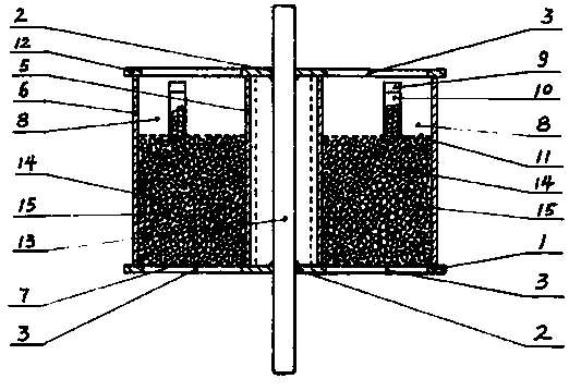
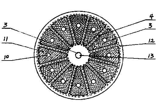
[0014] See figure 1 with figure 2 , in the runner of the runner dehumidifier of the present embodiment, a central circular hole 2 is provided in the middle of the circular lower supporting plate 1, and 12 equal holes are arranged on an annular plane close to the edge at an appropriate distance from the central circular hole 2. The fan-shaped ventilation openings 3 of the cloth and the spacer strips 4 that are radial to each other; the positioning sleeves 5 and the peripheral cylinders 6 of the same height are respectively provided on the inner side and the outer side near the fan-shaped ventilation openings 3; The upper surface of the air vent 3 is also provided with a material support mesh plate 7 connected to its edge, and a material partition plate 8 with the same height as it and connected with it is arranged between the positioning sleeve 5 and the peripheral cylinder 6. On each spacer slat 4, the middle part is provided with the cover material mesh plate 11 of the fee...


PUM


Abstract

The invention discloses a rotary wheel of a rotary wheel type dehumidifier. The rotary wheel comprises a circular lower supporting plate, wherein the circular lower supporting plate is provided with radial spaced battens and a central hole; fan-shaped vent holes are uniformly formed in the circular lower supporting plate; a positioning sleeve and a peripheral cylinder with the same height are arranged at the positions, close to the inner and outer sides of each fan-shaped vent hole; a material supporting mesh plate is arranged on the upper surface of each fan-shaped vent hole; a material separation plate is arranged on each spaced batten; the bottom edge and two side edges of each material separation plate are connected with the corresponding positioning sleeve and the corresponding peripheral cylinder, and the height of each material separation plate is the same as the heights of the corresponding positioning sleeve and the corresponding peripheral cylinder; a material covering mesh plate is arranged at an appropriate position above each material supporting mesh plate and is connected with each positioning sleeve, the corresponding peripheral cylinder and the adjacent material separation plate; a charging pipe with a pipe cover is arranged in the middle of each material covering mesh plate; the height of each charging pipe is slightly smaller than that of the corresponding material separation plate; an upper cover plate is arranged above a related part and is connected with the related part; the upper cover plate and the circular lower supporting plate are of the same shape and the same structure and are opposite to each other; a main shaft penetrates through central holes of the circular lower supporting plate and the upper cover plate and is connected with the central holes; a loading cavity is filled with spherical dehumidifying agent particles through the charging pipes.

Description

technical field [0001] The invention relates to the field of air humidity adjustment, in particular to a runner of a runner dehumidifier. Background technique [0002] The rotary dehumidifier is a kind of air dehumidification equipment commonly used at home and abroad for many years. The rotary wheel technology is the core technology of the rotary dehumidifier. Of course, the rotary wheel is the main component of the rotary dehumidifier. [0003] The rotor of the current rotary dehumidifier, see image 3 with Figure 4 Lithium chloride or silica gel or zeolite molecular sieve or activated alumina are attached to the honeycomb carrier made of ordinary fiber paper or asbestos fiber paper or glass fiber paper or ceramic fiber paper as the dehumidifier of the dehumidification wheel; although the production The process is simple, but because the rotary dehumidifier must use two "V" shaped isolation bars on the corresponding upper and lower surfaces to divide the rotary wheel int...

Claims


Application Information

Patent Timeline
Patent Type & Authority Applications(China)
IPC IPC(8): B01D53/06B01D53/26
Inventor 王斌王毅
Owner 太仓市洁益环卫设备有限公司
Why Eureka
Try Eureka