Semi-continuous casting of a steel strip

a technology of semi-continuous casting and steel strips, which is applied in the field of semi-continuous casting of strands, can solve the problems that the cooling rate of ingot casting is not realizable in continuously operated strand casting machines, and achieves the effects of low cooling rate, high operating cost and high quality of ingot casting

Inactive Publication Date: 2019-06-04
PRIMETALS TECH AUSTRIA GMBH
View PDF29 Cites 0 Cited by
  • Summary
  • Abstract
  • Description
  • Claims
  • Application Information

AI Technical Summary

Benefits of technology

[0014]Tests carried out by the applicant have shown that higher quality of ingot casting with respect to center segregation and porosity is primarily caused by a slow solidification rate and by solidification, directed from the strand start toward the strand end, in the central region of the ingot. The solidification in the center takes place in a globular manner, or with an axially oriented solidification front, such that any dendrites, which may occur and form bridges in the center and impede feeding of the melt, are avoided. Thread porosity in the center is thus largely precluded. In contrast, the properties during continuous casting are just the opposite. Extremely low cooling rates as in ingot casting are not realizable in continuously operated strand casting machines, since the machine length is limited for economic reasons. The higher cooling rate associated with the solidification that tends to be directed radially from the outside inward in continuous casting causes dendritic solidification and thus center segregation and porosity. Therefore, according to the prior art, large formats which are intended to be substantially free of center segregation and porosity, in particular thread porosity, are produced via the ingot route. The higher operating costs, lower output and disadvantages in the microstructure symmetry and purity of the ingot are accepted here.

Problems solved by technology

Extremely low cooling rates as in ingot casting are not realizable in continuously operated strand casting machines, since the machine length is limited for economic reasons.

Method used


Image

  • Semi-continuous casting of a steel strip
  • Semi-continuous casting of a steel strip
  • Semi-continuous casting of a steel strip

Examples


Embodiment Construction

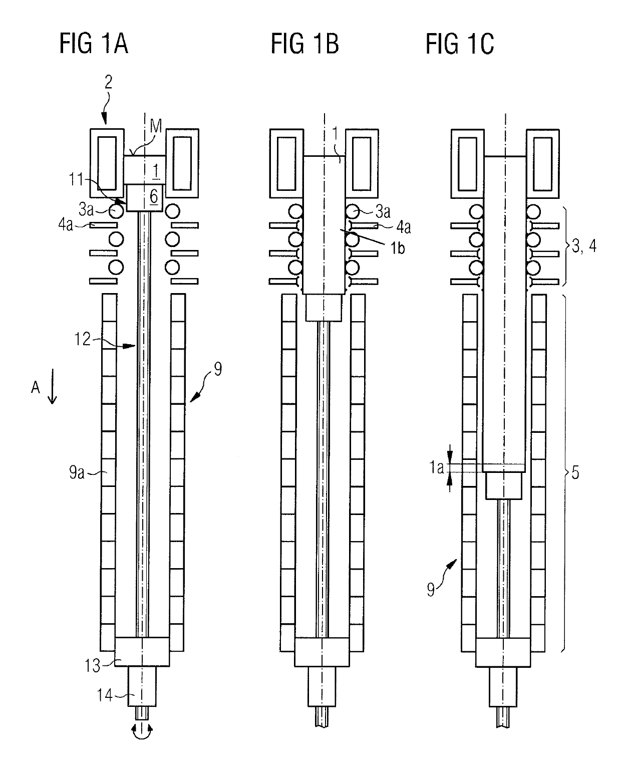
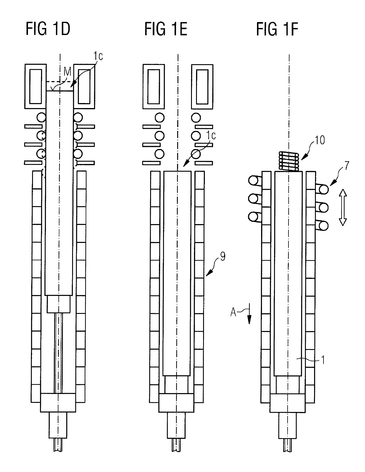
[0079]FIGS. 1A-1F show the method steps in the semi-continuous casting of a strand 1 in a strand casting machine.

[0080]In FIG. 1A, liquid steel is poured from a ladle tundish (not shown separately) via a submerged entry nozzle into a cooled open-ended mold 2, wherein, at the start of casting in the strand casting machine, the open-ended mold 2 is closed off in a fluid-tight manner by the dummy bar 6 such that a meniscus M is set in the mold. As a result of the liquid steel joining to the head of the dummy bar 6, a fully solidified strand start 1a (see FIG. 1C) is formed. As a result of the primary cooling of the cooled open-ended mold 2, the partially solidified strand 1b in FIG. 1B following the fully solidified strand start 1a counter to the extraction direction A is not fully solidified but has merely a thin strand shell and a liquid core. In order to keep the meniscus M in the mold 2 more or less constant in spite of the liquid steel flowing in via the submerged entry nozzle, th...


PUM

PropertyMeasurementUnit
opening angleaaaaaaaaaa
lengthaaaaaaaaaa

Abstract

A method for semi-continuous casting of a strand of steel in a strand casting machine and a strand casting machine that carries out the method, the method includes pouring liquid steel into a mold while closing off the mold by a bar to form a fully solidified strand start area followed by a partially solidified strand; extracting the partially solidified strand from the mold; supporting and guiding the partially solidified strand in the strand guide; at the end of the casting, ending the pouring of liquid steel into the mold and forming a strand end; extracting the strand end from the mold; ending the extraction of the strand end; ending the secondary cooling; providing controlled or regulated cooling of the partially solidified strand until full solidification of the strand; and discharging the strand from the strand casting machine.

Description

CROSS-REFERENCE TO RELATED APPLICATIONS[0001]The present application is a 35 U.S.C. §§ 371 national phase conversion of PCT / EP2015 / 051619, filed Jan. 27, 2015, which claims priority of European Patent Application No. 14162061.7, filed Mar. 27, 2014, the contents of which are incorporated by reference herein. The PCT International Application was published in the German language.TECHNICAL FIELD[0002]The present invention relates to a method for semi-continuous casting of a strand, preferably of an ingot, made of steel in a strand casting machine, and relates to a strand casting machine suitable therefor.[0003]In this specification and claims, semi-continuous casting refers to a process wherein a strand casting machine does not continuously produce a strand, but casts the strand semi-continuously or intermittently to produce a strand and then stops casting for a period of time, and then starts casting to produce another strand, etc.PRIOR ART[0004]The majority of steel produced nowaday...

Claims


Application Information

Patent Timeline
Patent Type & Authority Patents(United States)
IPC IPC(8): B22D11/041B22D11/055B22D11/12B22D11/128B22D11/124B22D11/22
CPCB22D11/041B22D11/055B22D11/225B22D11/1213B22D11/1281B22D11/124B22D11/128B22D11/20B22D11/08
Inventor BRUGGER, CHRISTIANHAHN, SUSANNEKLUGE, JENSKOGLER, HANS-PETERPOEPPL, JOHANNSHAN, GUOXINTANZER, SUSANNETHOENE, HEINRICHWIMMER, FRANZ
Owner PRIMETALS TECH AUSTRIA GMBH
Why Eureka
Try Eureka