
Liquid-crystal medium

a technology of liquid crystal medium and liquid crystal, which is applied in the direction of liquid crystal compositions, chemistry apparatus and processes, etc., can solve the problems of difficulty in mlc display, display size, and inability to prepare optimum phases in this way, and achieve short response times, good low-temperature behaviour, and good phase properties

Active Publication Date: 2019-05-28
MERCK PATENT GMBH
View PDF14 Cites 2 Cited by
  • Summary
  • Abstract
  • Description
  • Claims
  • Application Information

AI Technical Summary

Benefits of technology

[0020]There thus continues to be a great demand for MLC displays having very high specific resistance at the same time as a large working-temperature range, short response times and a low threshold voltage with the aid of which various grey shades can be produced.
[0366]The use of LC media containing polymerisable compounds allows the rapid establishment of a particularly low pretilt angle in PSA displays. In particular, the LC media exhibit significantly shortened response times, in particular also the grey-shade response times, in PSA displays compared with the media from the prior art.

Problems solved by technology

However, it has not been possible to prepare optimum phases easily in this way since no liquid-crystal materials having significantly negative dielectric anisotropy and adequate long-term stability were hitherto available.
The use of single-crystal silicon as substrate material restricts the display size, since even modular assembly of various part-displays results in problems at the joints.
Besides problems regarding the angle dependence of the contrast and the response times, difficulties also arise in MLC displays due to insufficiently high specific resistance of the liquid-crystal mixtures [TOGASHI, S., SEKIGUCHI, K., TANABE, H., YAMAMOTO, E., SORIMACHI, K., TAJIMA, E., WATANABE, H., SHIMIZU, H., Proc.
With decreasing resistance, the contrast of an MLC display deteriorates.
The disadvantage of the frequently-used MLC-TN displays is due to their comparatively low contrast, the relatively high viewing-angle dependence and the difficulty of generating grey shades in these displays.
This can lead to reduced VHR values and low reliability when the LC medium is exposed to external stress, especially during the LC display manufacturing process, for example in process steps like ODF (one drop filling), sealant curing, heat alignment and / or cell assembly.

Method used


Image

  • Liquid-crystal medium
  • Liquid-crystal medium
  • Liquid-crystal medium

Examples


example 2

[0428]An LC mixture with negative dielectric anisotropy is formulated as follows.

[0429]

CC-3-V23.00%cl.p.79.6° C.CC-3-V15.00%Δn0.1156CCY-3-O15.00%Δε−4.7CCY-3-O21.00%ε||3.9CCY-4-O22.50%K3 / K11.12CLY-3-O28.00%γ1133 mPa sCLY-3-O37.00%CPY-2-O210.00%CPY-3-O211.00%CY-3-O211.00%PY-3-O216.50%

[0430]To the above mixture are added 200 ppm of stabilizer S1-2a and 400 ppm of stabilizer S2a.

example 3

[0431]An LC mixture with negative dielectric anisotropy is formulated as follows.

[0432]

CC-3-V22.00%cl.p.90.6° C.CC-3-V15.00%Δn0.1063CCPC-333.00%Δε−4.6CCY-3-O16.00%ε||3.7CCY-3-O29.50%K3 / K11.18CCY-4-O29.00%γ1160 mPa sCPY-2-O210.00%CPY-3-O210.00%CY-3-O210.00%CY-5-O26.50%PY-3-O29.00%

[0433]To the above mixture are added 200 ppm of stabilizer S1-2a and 400 ppm of stabilizer S2a.

example 4

[0434]An LC mixture with negative dielectric anisotropy is formulated as follows.

[0435]

BCH-322.00%cl.p.80.1° C.CC-3-V29.00%Δn0.1051CCY-3-O17.00%Δε−4.5CCY-3-O36.00%ε||4.0CCY-4-O28.00%K3 / K11.13CLY-3-O26.00%γ1123 mPa sCPY-2-O210.00%CPY-3-O211.00%CY-3-O27.00%PY-3-O29.00%Y-4O-O45.00%

[0436]To the above mixture are added 150 ppm of stabilizer S1-2a and 400 ppm of stabilizer S2a.


PUM

PropertyMeasurementUnit
rotational viscositiesaaaaaaaaaa
rotational viscosityaaaaaaaaaa

Abstract

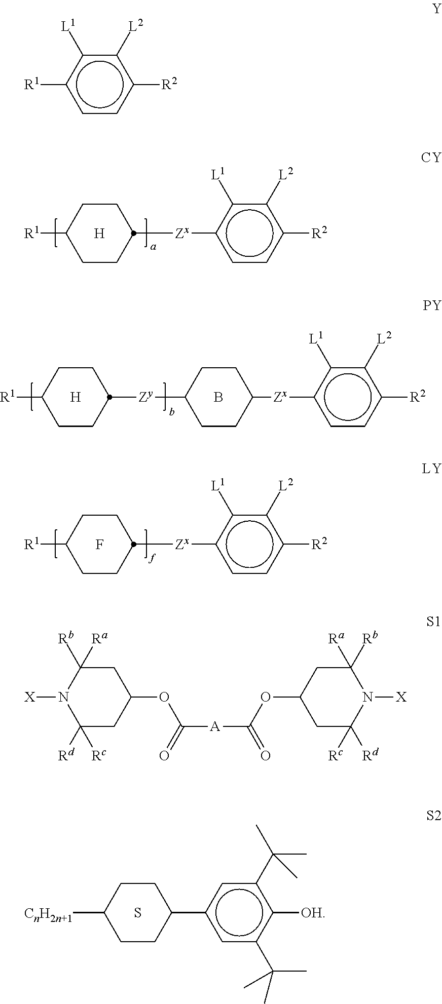
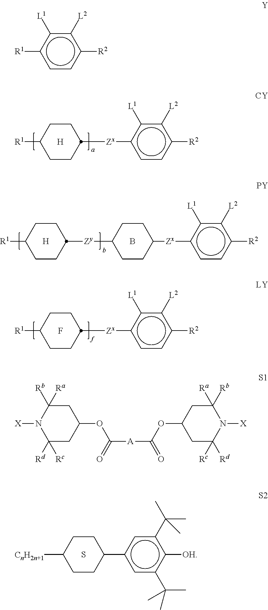
A liquid-crystalline medium, in particular based on a mixture of polar compounds, having compounds of formulae Y, CY, PY and / or LY, and compounds of formula S1 and / or S2:

Description

[0001]The use of the medium for an active-matrix display, in particular based on the VA, PSA, PS-VA, PA-VA, PALC, FFS, PS-FFS, IPS or PS-IPS effect.[0002]The invention relates to a liquid-crystalline medium, in particular based on a mixture of polar compounds, and to the use thereof for an active-matrix display, in particular based on the VA, PSA, PS-VA, PA-VA, PALC, FFS, PS-FFS, IPS or PS-IPS effect.[0003]Media of this type can be used, in particular, for electro-optical displays having active-matrix addressing based on the ECB effect and for IPS (in-plane switching) displays or FFS (fringe field switching) displays.[0004]The principle of electrically controlled birefringence, the ECB effect or also DAP (deformation of aligned phases) effect, was described for the first time in 1971 (M. F. Schieckel and K. Fahrenschon, “Deformation of nematic liquid crystals with vertical orientation in electrical fields”, Appl. Phys. Lett. 19 (1971), 3912). This was followed by papers by J. F. Kah...

Claims


Application Information

Patent Timeline
Patent Type & Authority Patents(United States)
IPC IPC(8): C09K19/42C09K19/54C09K19/06C09K19/12C09K19/20C09K19/30C09K19/34C09K19/04
CPCC09K19/54C09K19/062C09K19/12C09K19/20C09K19/3003C09K19/3066C09K19/3098C09K19/3402C09K19/3472C09K2019/0466C09K2019/122C09K2019/123C09K2019/124C09K2019/3004C09K2019/3016C09K2019/3024C09K2019/3025C09K2019/3027C09K2019/3078C09K2019/3422C09K2019/3425C09K19/46C09K19/3441
Inventor HUNG, GAVINHUANG, LAWRENCENIEN, MAX
Owner MERCK PATENT GMBH
Learn More