Eureka AIR delivers breakthrough ideas for toughest innovation challenges, trusted by R&D personnel around the world.

Sintered Soft Magnetic Powder Molded Body

a magnetic powder and soft technology, applied in the direction of magnets, magnetic materials, magnetic bodies, etc., can solve the problems of generating heat for the hysteresis that is shown, not negligible, and not advantageous for steps, and achieve excellent alternate current magnetic properties, low iron loss, and high specific resistance

Active Publication Date: 2010-07-01
MITSUBISHI STEEL MFG CO LTD
View PDF7 Cites 1 Cited by
  • Summary
  • Abstract
  • Description
  • Claims
  • Application Information

AI Technical Summary

Benefits of technology

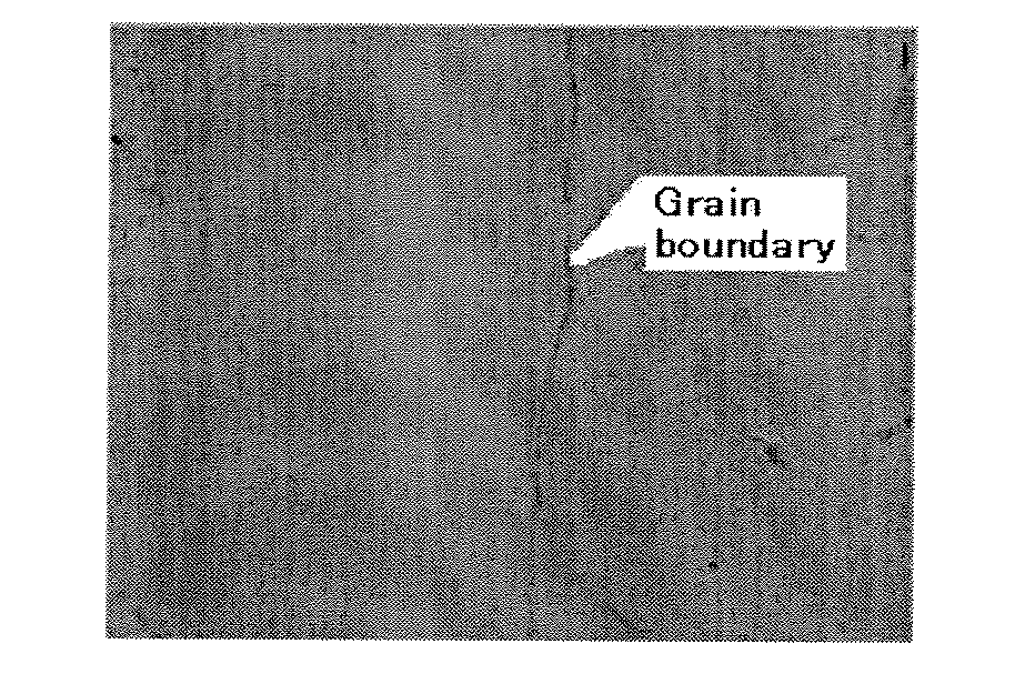
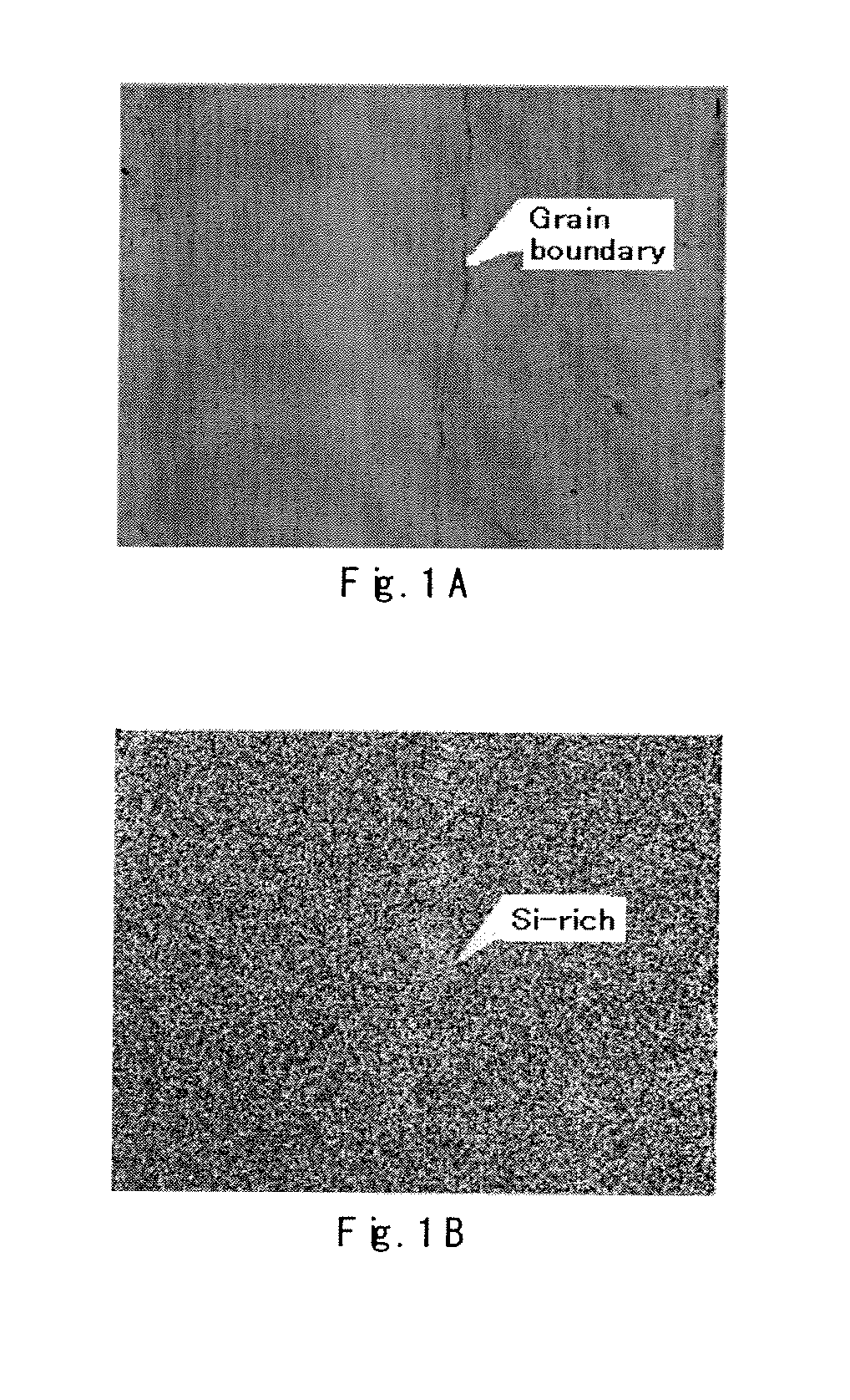
The present invention relates to a sintered soft magnetic powder molded body using a soft magnetic powder. The technical effect of the invention is to provide a sintered soft magnetic powder molded body with high specific resistance and excellent alternate current magnetic property, i.e., low iron loss, to suppress generation of heat due to eddy current and reduce electric power loss during use. The invention achieves this by using a composition containing Fe, 44 to 50% by mass of Ni, and 2 to 6% by mass of Si, wherein Si is unevenly distributed among particles. The specific means for achieving this include mixing a metal powder containing Fe and Ni with an Si powder having an average particle diameter of from 1 / 10 to 1 / 100 of the average particle diameter of the metal powder, and molding and sintering the mixture. The resulting sintered soft magnetic powder molded body has high specific resistance and low iron loss.

Problems solved by technology

Furthermore, hysteresis loss included in iron loss, i.e., generation of heat for the hysteresis that is shown when the magnetic area of the iron core changes the direction of the magnetic field by alternating magnetic field is also not negligible.
Meanwhile, in the case of a solid metal made of melted materials, it is necessary to perform processing such as cutting in order to obtain a desired shape and machine processing is inevitable, which is not advantageous for the steps.

Method used


Image

  • Sintered Soft Magnetic Powder Molded Body
  • Sintered Soft Magnetic Powder Molded Body

Examples


example 1

[0068]Si micropowder A was added to a permalloy PB-based raw material powder (Fe-50Ni-2Si) having an average particle diameter D50 of 150 μm so that Si was adjusted to 3% by mass, and mixed. Further, 0.5% by mass of a zinc stearate was added as a lubricant to the mixed powder under room temperature, and mixed. The obtained mixed powder was put into a mold at room temperature and pressed at a surface pressure of 15 t / cm2to give a pressed product having a ring shape. The pressed product was sintered at 1300° C. for 60 minutes to give a sintered product, a molded body.

[0069]For the obtained sintered product, direct current magnetic property, iron loss and specific resistance were measured as follows. The results of the measurements are shown in the following Table 1.

[0070]—1) Direct current magnetic property—

[0071]Using a direct current magnetic property testing apparatus (trade name: TYPE SK-130, manufactured by Metron Inc.), the magnetic flux density B2000at the magnetizing force of ...

example 2

[0076]A sintered product was obtained by pressing and sintering in a similar manner to Example 1, except that Si micropowder A was replaced with Si micropowder B in Example 1. Furthermore, measurement and evaluation were carried out in a similar manner to Example 1, and the results are shown in the following Table 1.

example 3

[0077]A sintered product was obtained by pressing and sintering in a similar manner to Example 1, except that Si micropowder A was replaced with Si micropowder C in Example 1. Furthermore, measurement and evaluation were carried out in a similar manner to Example 1, and the results are shown in the following Table 1.


PUM

PropertyMeasurementUnit
particle diameteraaaaaaaaaa

Abstract

A sintered soft magnetic powder molded body having a composition containing Fe, 44 to 50% by mass of Ni and 2 to 6% by mass of Si, or a composition containing Fe and 2 to 6% by mass of Si, wherein the Si is unevenly distributed among particles, is provided.

Description

TECHNICAL FIELD[0001]The present invention relates to a sintered soft magnetic powder molded body using a soft magnetic powder.BACKGROUND ART[0002]Until now, stainless materials made of a melted stainless have been widely known as a sintered electromagnetic stainless material obtained by sintering. Electromagnetic stainless materials are used, for example, as magnetic parts such as electromagnetic valves, injectors for injecting fuels and various actuators.[0003]Recently, frequency during use and higher harmonic wave component for such magnetic parts have been increased. In accordance with this, for example, loss of electric power and generation of heat due to eddy current generated when alternate current is applied to an iron core having a coil wound around the core tend to increase. Furthermore, hysteresis loss included in iron loss, i.e., generation of heat for the hysteresis that is shown when the magnetic area of the iron core changes the direction of the magnetic field by alte...

Claims


Application Information

Patent Timeline
Patent Type & Authority Applications(United States)
IPC IPC(8): H01F1/147C22C38/08C22C38/02
CPCB22F2998/10C22C1/1042C22C19/03C22C33/0285C22C38/02C22C38/08H01F1/14741H01F1/14766H01F1/22C22C1/0433C22C1/05B22F9/082C22C33/0271B22F3/02B22F3/10C22C1/04C22C33/02
Inventor UNOKI, KENICHIYAMAMOTO, SOICHISODA, YUJIFUKUDA, MASAKATSU
Owner MITSUBISHI STEEL MFG CO LTD
Why Eureka
Eureka Blog
Learn More