
Reset domain crossing management using unified power format

a domain crossing and management technology, applied in the field of reset domain crossing management using unified power format, can solve the problems of reducing the design and debug cycle, adding significant time and expense, and erroneous data transfers, so as to reduce the design burden on circuit designers, eliminate redundant isolation gates, and simplify the management of reset domain crossings

Active Publication Date: 2019-05-14
SYNOPSYS INC
View PDF5 Cites 0 Cited by
  • Summary
  • Abstract
  • Description
  • Claims
  • Application Information

AI Technical Summary

Benefits of technology

[0011]The present invention greatly simplifies the management of reset domain crossings (RDCs) in a circuit design by way of utilizing one or more functions conventionally performed by Unified Power Format (UPF) software tools to automatically identify RDCs that can be addressed using isolation resources that are “shared” with corresponding power domain crossings (PDCs). Similar to conventional approaches, each circuit design processed by the enhanced EDA software tool is defined using both an HDL description that is written using an established HDL format (e.g., VHDL, Verilog or System Verilog) and a UPF description that is written using an established UPF format (e.g., IEEE Standard 1801-2009), and the enhanced EDA software tool implements analysis and verification methodologies that process the HDL and UPF descriptions in a manner similar to the approach utilized by conventional EDA software tools. The enhanced EDA design tools differs from conventional EDA software tools by way of introducing a novel technique for performing RDC management that utilizes the UPF description to identify instances where an RDC isolation solution may be co-generated with an associated PDC isolation solution, thereby reducing design burdens on circuit designers by eliminating redundant isolation gates, and improving circuit performance by eliminating signal delays generated by redundant isolation gates.
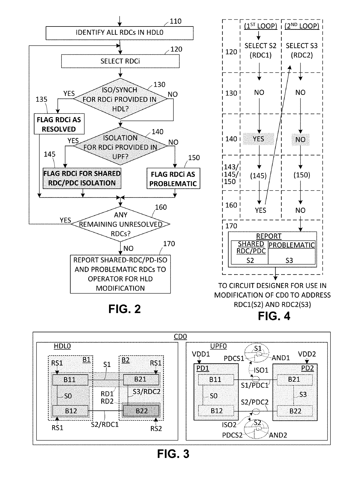
[0012]According to an embodiment of the present invention, both an initial HDL description and an initial UPF description of a circuit design are utilized to automatically identify each signal of the circuit design that forms both an RDC (i.e., as identified by way of the initial HDL description) and a PDC (i.e., as identified in the UPF description), and then a report is generated that notifies a circuit designer of all such signals so that potentially redundant isolation gates are avoided. In one embodiment, the initial HDL description for the initial circuit design is utilized to identify all RDCs that have not yet been resolved (i.e., all RDCs that have not yet been assigned isolation or synchronization solutions in the initial HDL description), and then the UPF description is analyzed to determine if each unresolved RDC signal identified in the initial HDL description also forms an associated PDC (i.e., the same signal is both identified as an RDC in the HDL description and as a PDC in the UPF description). Each signal that forms both an RDC and a PDC is flagged as a candidate for shared RDC / PDC isolation (i.e., the circuit designer is notified that a single isolation gate may be efficiently utilized to provide both reset domain and power domain isolation functions, which reduces design time and delays by avoiding the generation of unnecessary redundant isolation gates). In addition, all RDC signals that have not yet been addressed using isolation or synchronization circuitry, and do not have associated PDC functions, are flagged as problematic signals that must also be addressed before verification. Once all of the RDC signals have been processed, a report is generated and / or transmitted to the circuit designer indicating all RDC signals that may be addressed using shared isolation circuits and / or problematic signals that require concerted attention, thereby providing the circuit designer with an automatically generated comprehensive list of all unresolved RDC issues. Accordingly, in addition to automatically generating a comprehensive list of unresolved RDC issues, the present invention reduces design burdens by allowing circuit designers to efficiently utilize, wherever possible, “shared” isolation strategies (e.g., AND logic gates) that can be cooperatively controlled to perform both power control and reset control isolation functions, thereby minimizing the final circuit design size and signal delays by way of eliminating redundant RDC / PDC isolation gates.
[0013]In another embodiment, the present invention proposes the use of a modified UPF description in which reset domains identified in the initial HDL description are modeled as pseudo-power domains in the modified UPF descriptions, thereby facilitating the automated generation of RDC isolation resources and shared RDC / PDC isolation solutions using techniques similar to those currently used by UPF tools to provide PDC isolation solutions.
[0014]Also described herein are specific embodiments of processes and systems utilized when both power and reset domain crossings are present in a circuit design, and function to automatically modify the circuit design as needed to provide efficient (shared) isolation circuits that ensure stability for both power and reset domain crossings in an integrated circuit subsequently fabricated using the circuit design. In one embodiment of the invention, the power domain crossing information is utilized to verify and efficiently modify (if needed) the RDCs such that all RDCs are provided with safe data paths using power domain isolation resources (i.e., isolation gates / controls). Specifically, the present invention recognizes that, when power and reset domain crossings overlap, both the power domain crossing and the overlapping reset domain crossing may be made safe using a shared isolation circuit (cell) and / or gate. According to this embodiment, related information from the UPF description is applied to RDC analysis to identify where RDC and power domain boundaries overlap. If a common isolation circuit can be formed to make both crossings safe, the common circuit is applied to the RDC analysis in order to reduce noise (i.e., by way of eliminating a redundant second isolation circuit). If a common isolation circuit is not present, a new circuit is optionally generated in the modified UPF to resolve the unsafe RDC. Accordingly, the circuit design is automatically modified to include a new or revised UPF description including all isolation strategies needed to ensure stable RDC operations in the subsequently fabricated IC. Consequently, the present invention reduces verification efforts by way of coordinating UPF and RDC verification processes, and facilitates the efficient production of improved ICs by automatically modifying the UPF circuit design to include shared isolation cells that also remove unsafe RDCs, which reduces noise.

Problems solved by technology

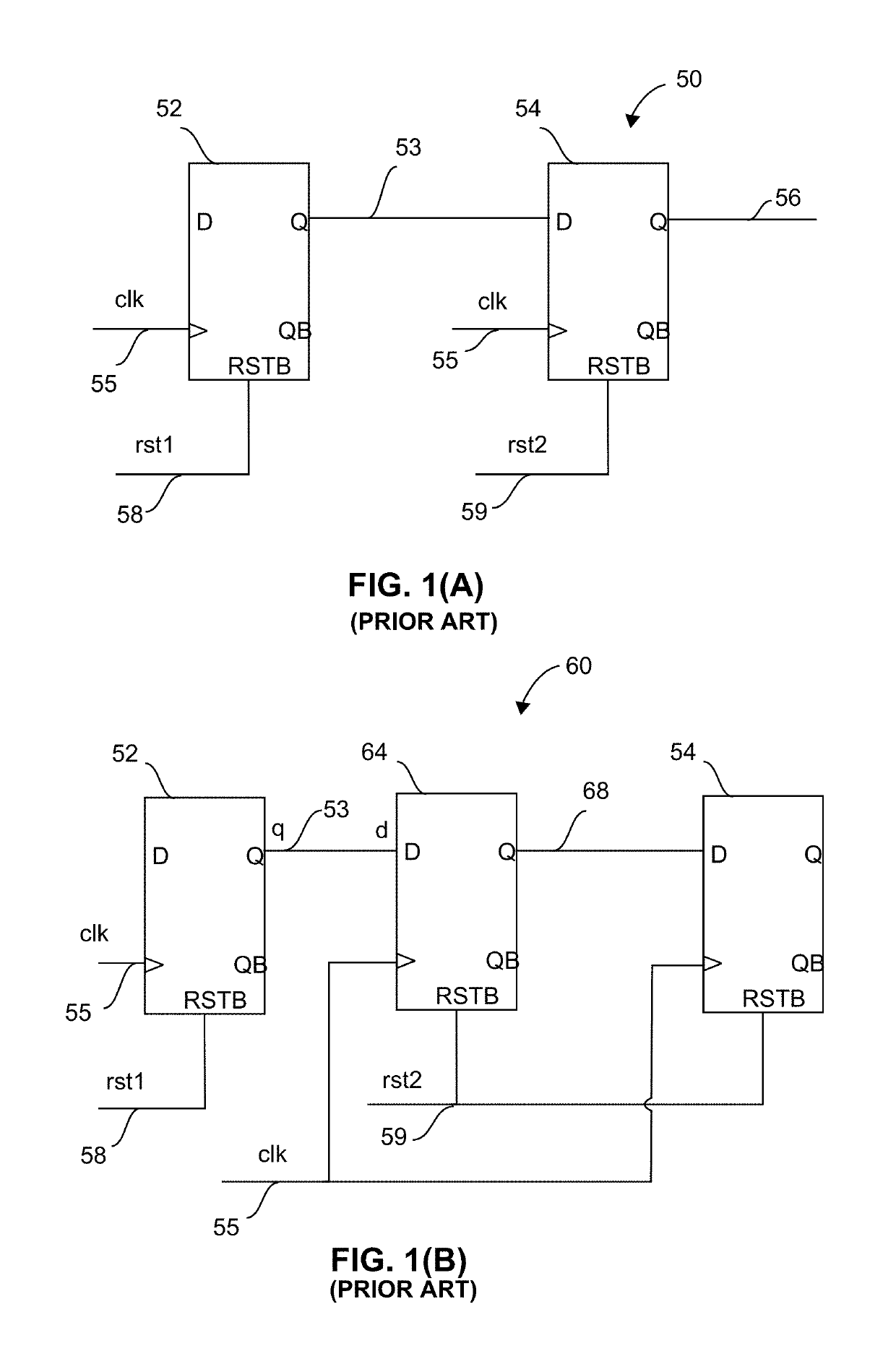
Metastability occurs when digital signals passed between circuit elements (e.g., from one flip-flop to a second flip flop) are unable to settle into a stable ‘0’ or ‘1’ logic level within the time required for proper circuit operation, thereby resulting in erroneous data transfers.
Asynchronous reset crossings within a same clock domain can also cause metastability.
As a consequence, Reset Domain Crossing (RDC) issues are causing more and more design errors.
Such errors can add significant time and expense to the design and debug cycles, and may even find their way into the silicon, necessitating costly re-spins.
Problems arise when signals cross from one domain to another.
Thus containing unstable (metastable) behavior of circuit.
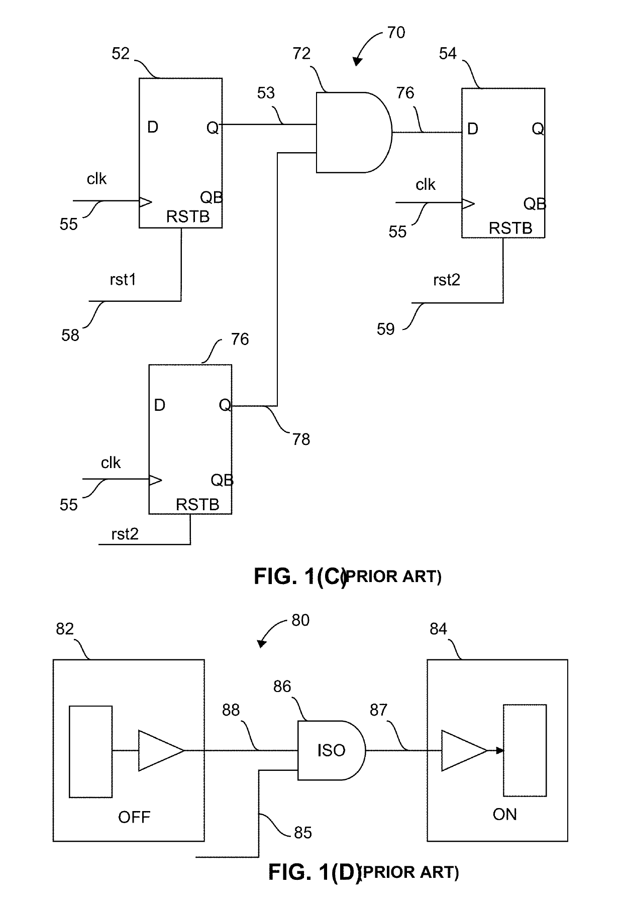
The generation of separate circuitry thus generates an unnecessarily high design burden on the designer, and can lead to unnecessarily larger circuit designs and signal delays due, for example, to redundant isolation gates.

Method used


Image

  • Reset domain crossing management using unified power format
  • Reset domain crossing management using unified power format
  • Reset domain crossing management using unified power format

Examples


Embodiment Construction

[0033]“RDC” in this context refers to Reset Domain Crossing, an asynchronous reset crossing within a same clock domain or different clock domain.

[0034]“UPF” in this context refers to Unified Power Format. UPF is described in IEEE Standard 1801-2009, based on Accellera's Unified Power Format (UPF), and allows designers to describe low power designs and improve the way complex integrated circuits are designed, verified and implemented. UPF covers the Register Transfer Level (RTL) up through more detailed levels of implementation and verification.

[0035]FIG. 2 illustrates an efficient methodology for addressing RDCs and PDCs in an initial circuit design according to an exemplary embodiment of the present invention. In general, blocks 110 to 160 of FIG. 2 depict a loop during which both an initial HDL description and an initial UPF description of a circuit design are utilized to automatically identify each signal of the initial circuit design that forms both an RDC in the HDL description...


PUM


Abstract

Information from a circuit design's unified power format (UPF) description is utilized to automate the management of reset domain crossings (RDCs). The UPF description is utilized to identify signals that generate both RDC and power domain crossings (PDCs), thereby allowing a circuit designer to efficiently utilize a common (shared) isolation circuit that functions to manage both the RDC (i.e., during reset functions) and the PDC (i.e., during power management functions). A modified UPF description is introduced that facilitates automated management of RDC issues by treating the reset domains as pseudo-power domains, and utilizing UPF analysis and verification tools to automatically generate both shared and non-shared resources for both RDC and PDC issues.

Description

RELATED APPLICATION[0001]This application claims priority from U.S. Provisional Patent Application 62 / 357,296, entitled “UPF AWARE RESET DOMAIN CROSSING”, which was filed on Jun. 30, 2016, and is incorporated by reference herein.BACKGROUND[0002]Metastability occurs when digital signals passed between circuit elements (e.g., from one flip-flop to a second flip flop) are unable to settle into a stable ‘0’ or ‘1’ logic level within the time required for proper circuit operation, thereby resulting in erroneous data transfers. A well-known source of metastability occurs when signals are passed from a first circuit element controlled by one clock signal to a second circuit element controlled by a second clock signal. Clock domain crossings (CDCs) and power domain crossings (PDCs) are well-known sources of metastability. Asynchronous reset crossings within a same clock domain can also cause metastability. Use of asynchronous resets is becoming more prevalent because of the wider use of mul...

Claims


Application Information

Patent Timeline
Patent Type & Authority Patents(United States)
IPC IPC(8): G06F17/50
CPCG06F17/5022G06F2217/62G06F17/505G06F30/33G06F30/396G06F30/327
Inventor SHAH, DEEPGUPTA, NAMITSARWARY, MOHAMED SHAKER
Owner SYNOPSYS INC
Learn More