
Thermal and power optimization for linear regulator

a technology of linear regulators and power optimization, applied in the direction of electric variable regulation, process and machine control, instruments, etc., can solve the problem of not increasing the power supply of led strings, etc., and achieve the effect of reducing power consumption, increasing output, and reducing outpu

Active Publication Date: 2019-04-30
DIODES INC
View PDF18 Cites 4 Cited by
  • Summary
  • Abstract
  • Description
  • Claims
  • Application Information

AI Technical Summary

Benefits of technology

The patent text describes a power supply for LED lights that provides efficient power to multiple LED strings. The power supply includes a power converter, multiple-channel linear regulators, and a control circuit. The control circuit monitors the current in each string of LEDs and adjusts the voltage output accordingly to maintain a regulated output. This allows for real-time control of low dropout voltages at different loading and temperature conditions to lower power consumption and improve the efficiency of the power supply. The invention provides improved power efficiency for LED lighting applications.

Problems solved by technology

It cannot increase the power supply to the LED strings when the operating condition changes and requires a higher power supply.

Method used


Image

  • Thermal and power optimization for linear regulator
  • Thermal and power optimization for linear regulator
  • Thermal and power optimization for linear regulator

Examples


Embodiment Construction

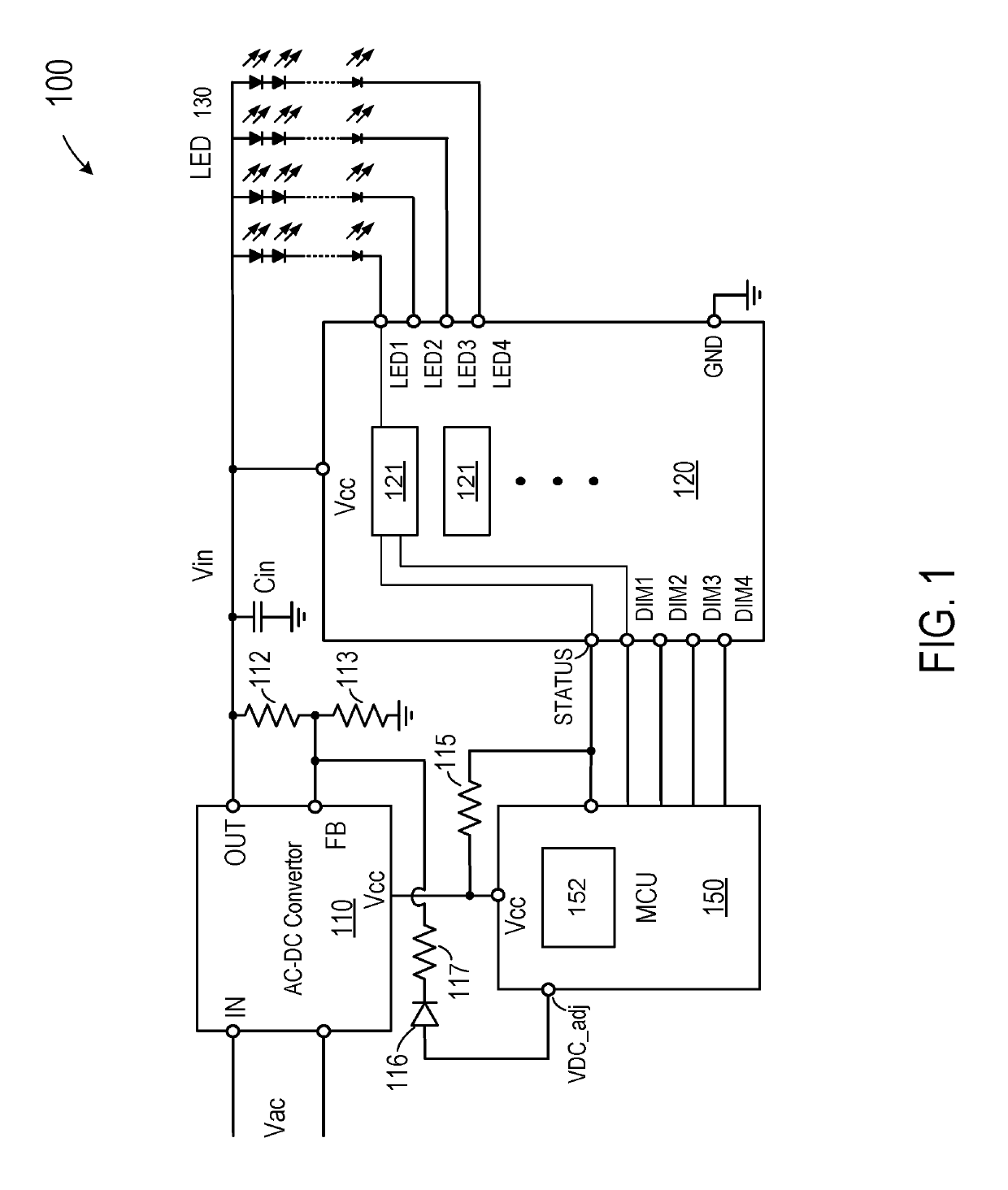
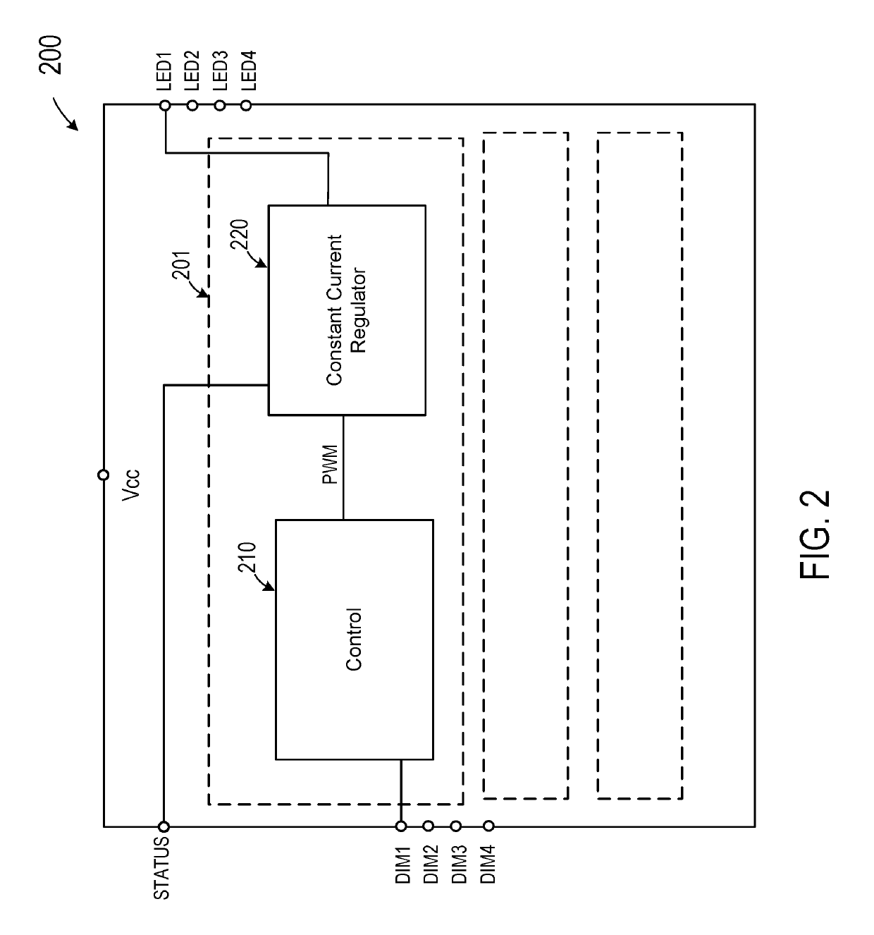
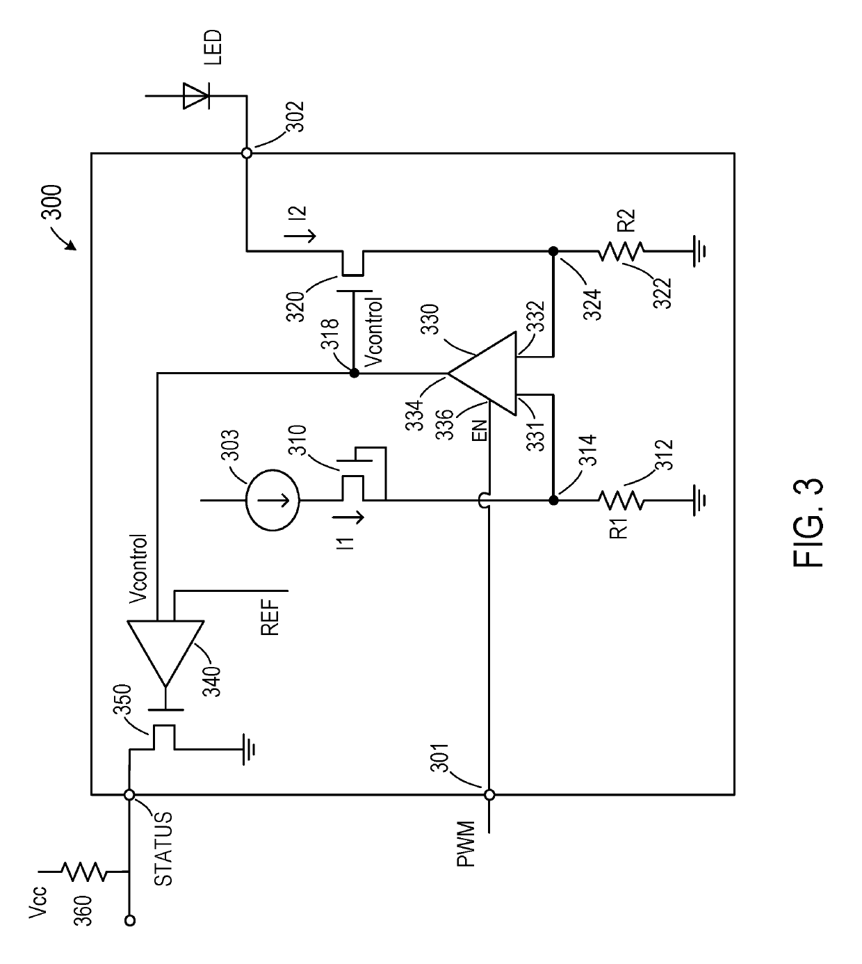
[0034]FIG. 1 is a simplified schematic diagram depicting a power supply for driving an LED (light-emitting-diode) lamp load that embodies certain aspects of this invention. As shown in FIG. 1, power supply 100 includes a power converter 110, e.g., an AC-DC converter, coupled to an AC input source Vac for providing a DC voltage source Vin to an LED load 130 including a plurality of LED strings. Power converter 110 includes a power input node IN coupled to the AC input power source, an output node OUT coupled to a first end of each of the plurality of LED strings, and a feedback node FB for receiving a feedback signal derived from the output node. The power converter converts an AC or DC input voltage at the power input node to an output DC voltage on the output node in response to, in part, the feedback signal. In this embodiment, the feedback signal is derived from the DC output voltage Vin through a voltage divider that includes resistors 112 and 113. For simplicity, in this descri...


PUM


Abstract

A power supply includes a power converter configured to convert an input voltage to a target output DC voltage in response to a feedback signal, the feedback signal having a value. The power supply also includes a regulator coupled to the power converter and configured to generate an output power status signal, which maybe in one of two states depending whether an output current from the regulator is above or below a target current over a preset time duration. Further, a control circuit is coupled to the power converter and to the regulator and configured to increment or decrement the value of the feedback signal depending on the state of the power status signal.

Description

CROSS-REFERENCES TO RELATED APPLICATIONS[0001]This application claims priority to U.S. Provisional Patent Application No. 62 / 365,373, filed Jul. 21, 2016, entitled “THERMAL AND POWER OPTIMIZATION FOR LINEAR REGULATOR,” commonly owned and incorporated by reference herein in its entirety. This application is also a continuation-in-part application of U.S. patent application Ser. No. 15 / 094,817, filed Apr. 8, 2016, entitled “POWER OPTIMIZATION FOR LINEAR REGULATOR,” which claims priority to U.S. Provisional Patent Application No. 62 / 126,440, filed Apr. 9, 2015, entitled “POWER OPTIMIZATION FOR LINEAR REGULATOR,” commonly owned and incorporated by reference herein.[0002]This application is also related to U.S. patent application Ser. No. 15 / 049,590 filed Feb. 22, 2016, entitled “ANALOG AND DIGITAL DIMMING CONTROL FOR LED DRIVER” which claims priority to U.S. Provisional Patent Application No. 62 / 126,440, filed Feb. 27, 2015, entitled “ANALOG AND DIGITAL DIMMING CONTROL FOR LED DRIVER” c...

Claims


Application Information

Patent Timeline
Patent Type & Authority Patents(United States)
IPC IPC(8): H05B37/02H05B33/08G05F1/46H05B44/00
CPCH05B33/0812G05F1/461H05B33/0827H05B33/0845H05B33/0815Y02B20/345H05B45/46Y02B20/30H05B45/18H05B45/397H05B45/395H05B45/37
Inventor WANG, ADRIANSU, CHIEN-JEN
Owner DIODES INC
Learn More