
Optimization method and system for overlay error compensation

a technology of error compensation and optimization method, which is applied in the field of photolithography technology, can solve the problems of oos (out of spec) problems of overlay error between subsequent layers, and achieve the effects of reducing the overlay oos rate and process rework rate, improving overlay performance, and improving overlay performan

Active Publication Date: 2019-04-16
SHANGHAI HUALI MICROELECTRONICS CORP
View PDF2 Cites 1 Cited by
  • Summary
  • Abstract
  • Description
  • Claims
  • Application Information

AI Technical Summary

Benefits of technology

The present invention provides an optimization method and system for overlay error compensation that can prevent OOC problems of overlay accuracy, decrease process rework rate, and reduce overlay residue. By considering the 1st layer within-shot overlay errors and optimizing the process parameters, the method and system can improve the overlay performance between the tool to tool matching and lot to lot matching during the lithographic process for the subsequent production lots. Additionally, the method and system can minimize the overlay residue which cannot be compensated.

Problems solved by technology

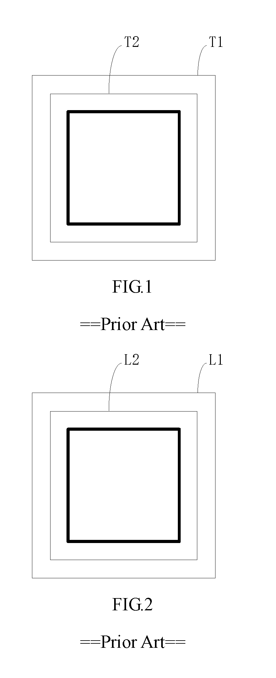
However, current APC systems merely compensate the overlay error between the current layer and a previous layer, without considering the overlay error between the actual exposed pattern and the theoretical exposed pattern of the first layer.
As a result, OOS (out of spec) problems of the overlay error between the subsequent layers may occur.

Method used


Image

  • Optimization method and system for overlay error compensation
  • Optimization method and system for overlay error compensation
  • Optimization method and system for overlay error compensation

Examples


Embodiment Construction

[0041]The invention will be described in further details hereinafter with respect to the embodiments and the accompanying drawings of FIGS. 3-13.

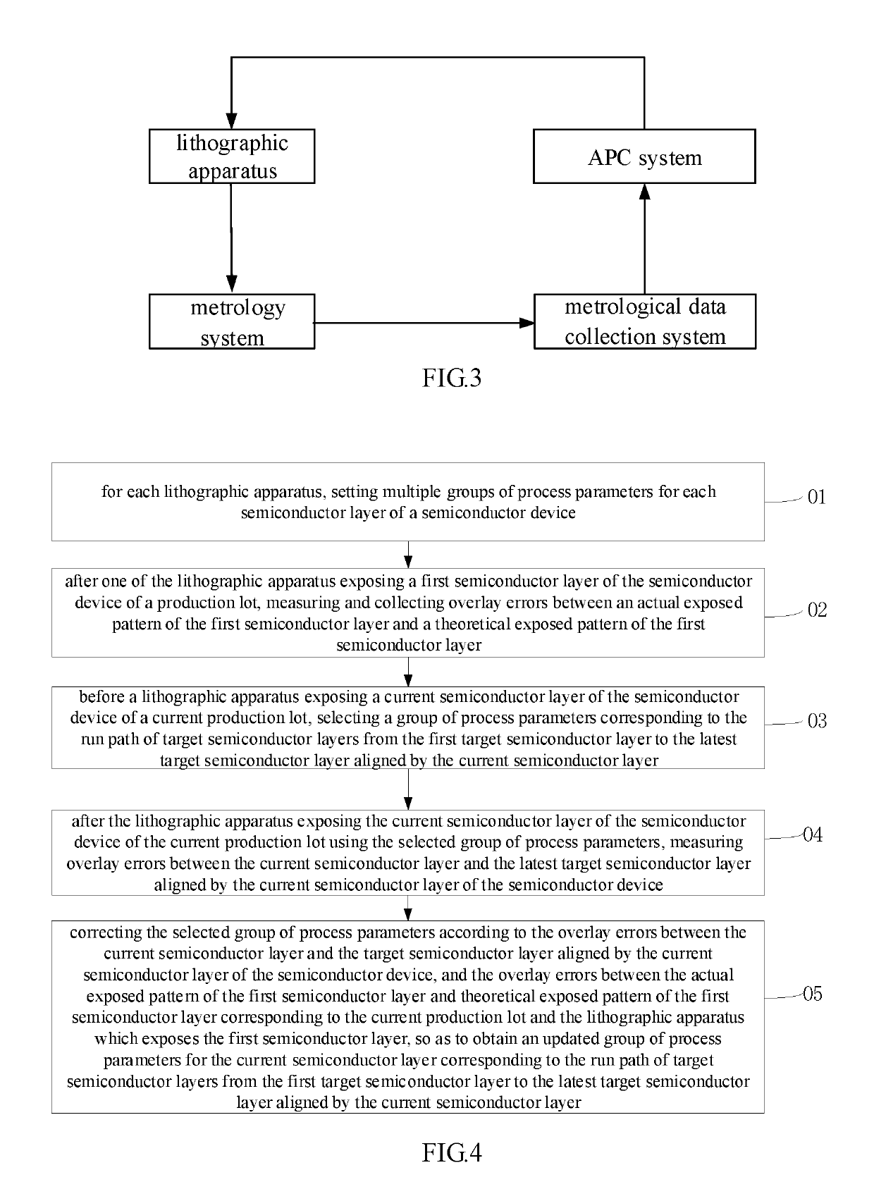
[0042]Referring to FIG. 1, an optimization system for overlay error compensation is shown. The optimization system for overlay error compensation may include multiple lithographic apparatus. Each lithographic apparatus may be a stepper or scanner-type lithographic apparatus configured to process one or more semiconductor layers on a substrate to generate a semiconductor device.

[0043]The optimization system may further include a metrology system and a metrological data collection system. The metrology system is configured to perform semiconductor layer overlay error measurements. The metrological data collection system is configured to collect the overlay error values.

[0044]The optimization system may further include an APC system. The APC system is configured to automatically adjust the process parameters to compensate the overlay errors.

[0...


PUM

PropertyMeasurementUnit
field rotationaaaaaaaaaa
semiconductoraaaaaaaaaa

Abstract

An optimization method for overlay error compensation is disclosed. The method comprises setting process parameters for each semiconductor layer of a semiconductor device corresponding to a run path formed by different lithographic apparatus which sequentially process target semiconductor layers from a first target layer to a latest target layer; measuring overlay errors between an actual and a theoretical exposed patterns of the first semiconductor layer; selecting a group of process parameters corresponding to the run path from the first target layer to the latest target layer aligned by the current semiconductor layer; after exposing the current semiconductor layer using the selected process parameters, measuring overlay errors between the current semiconductor layer and its target layer; and correcting the selected process parameters according to the overlay errors between the current semiconductor layer and its target layer, and the overlay errors between the actual and theoretical exposed patterns of the first semiconductor layer.

Description

CROSS-REFERENCE TO RELAYED APPLICATION[0001]This application claims the priority benefit of China application serial no. 201710187899.6, filed Mar. 27, 2017. All disclosure of the China application is incorporated herein by reference.FIELD OF THE INVENTION[0002]The present invention relates to the field of photolithography technology, and more particularly to an optimization method and system for overlay error compensation.BACKGROUND OF THE INVENTION[0003]Generally, advanced process control (APC) systems are adopted to compensate overlay errors for photolithographic apparatus. The APC system receives the measured overlay errors of a production lot of semiconductor devices and calculates overlay model parameters for the production lot.[0004]However, current APC systems merely compensate the overlay error between the current layer and a previous layer, without considering the overlay error between the actual exposed pattern and the theoretical exposed pattern of the first layer. As sh...

Claims


Application Information

Patent Timeline
Patent Type & Authority Patents(United States)
IPC IPC(8): G03F7/20H01L21/68H01L21/66
CPCG03F7/70633G03F7/70625H01L22/34H01L22/12H01L21/68G03F7/70433G03F7/70508G03F9/7003H01L22/20
Inventor DAI, YUNQINGWANG, JIAN
Owner SHANGHAI HUALI MICROELECTRONICS CORP
Learn More