
Fuel cell architectures, monitoring systems, and control logic for characterizing fluid flow in fuel cell stacks

a fuel cell and stack technology, applied in the field of fuel cell systems, can solve the problems of reducing system efficiency, reducing system reliability, and reducing stack voltage, so as to improve system reliability, reduce stack emissions, and increase stack efficiency

Active Publication Date: 2019-04-02
GM GLOBAL TECH OPERATIONS LLC
View PDF33 Cites 0 Cited by
  • Summary
  • Abstract
  • Description
  • Claims
  • Application Information

AI Technical Summary

Benefits of technology

The patent describes a system for detecting the flow of fuel in a vehicle's fuel cell system using voltage monitoring. This approach helps improve the reliability and efficiency of the system by providing precise information about the fuel's flow and characterization, even during difficult operating conditions. By using this method, the system can better control the flow and reduce emissions, while also minimizing the impact of environmental variations and component failure. Overall, this approach enhances the vehicle's performance and reduces costs.

Problems solved by technology

With this additional hydrogen input, however, the amount of hydrogen in the anode's exhaust is likely to increase, which can lead to reduced system efficiency.
Stack voltage is typically insensitive to hydrogen concentration due to very fast hydrogen-oxidation reaction kinetics and low hydrogen mass transfer.
Flow rate comparisons, however, have limited accuracy due to system leakage and operating condition fluctuations (e.g., temperature, current density, relative humidity, pressure, etc.).
As per the dedicated sensing electronics, nitrogen and hydrogen sensors are very expensive components and relatively unreliable devices for estimating fuel cell states, such as determining the concentration of hydrogen or oxygen in sections of a fuel cell system over the operational life of the system.

Method used


Image

  • Fuel cell architectures, monitoring systems, and control logic for characterizing fluid flow in fuel cell stacks
  • Fuel cell architectures, monitoring systems, and control logic for characterizing fluid flow in fuel cell stacks

Examples


Embodiment Construction

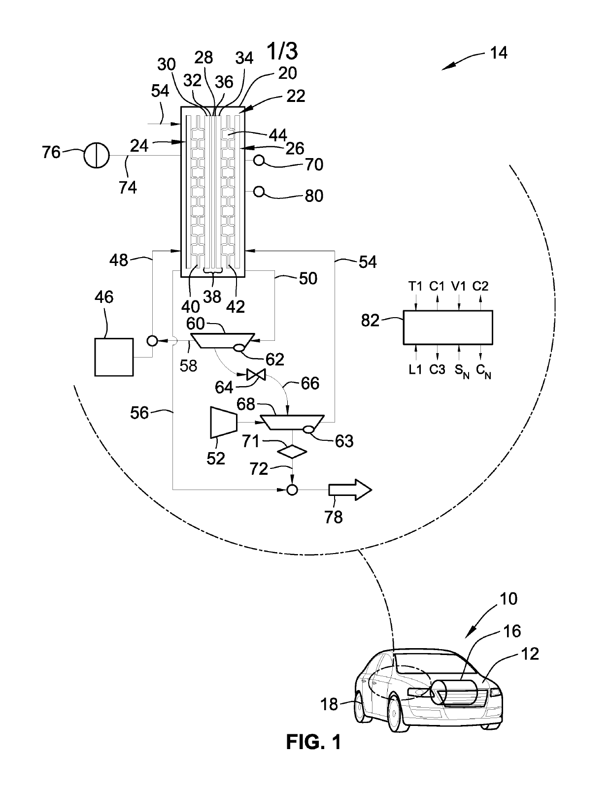
[0018]This disclosure is susceptible of embodiment in many different forms. There are shown in the drawings and will herein be described in detail representative embodiments of the disclosure with the understanding that these representative embodiments are to be considered an exemplification of the principles of the disclosure and are not intended to limit the broad aspects of the disclosure to the embodiments illustrated. To that extent, elements and limitations that are disclosed, for example, in the Abstract, Summary, and Detailed Description sections, but not explicitly set forth in the claims, should not be incorporated into the claims, singly or collectively, by implication, inference or otherwise. For purposes of the present detailed description, unless specifically disclaimed: the singular includes the plural and vice versa; the words “and” and “or” shall be both conjunctive and disjunctive; the word “all” means “any and all”; the word “any” means “any and all”; and the word...


PUM

PropertyMeasurementUnit
current densityaaaaaaaaaa
pressure biasaaaaaaaaaa

Abstract

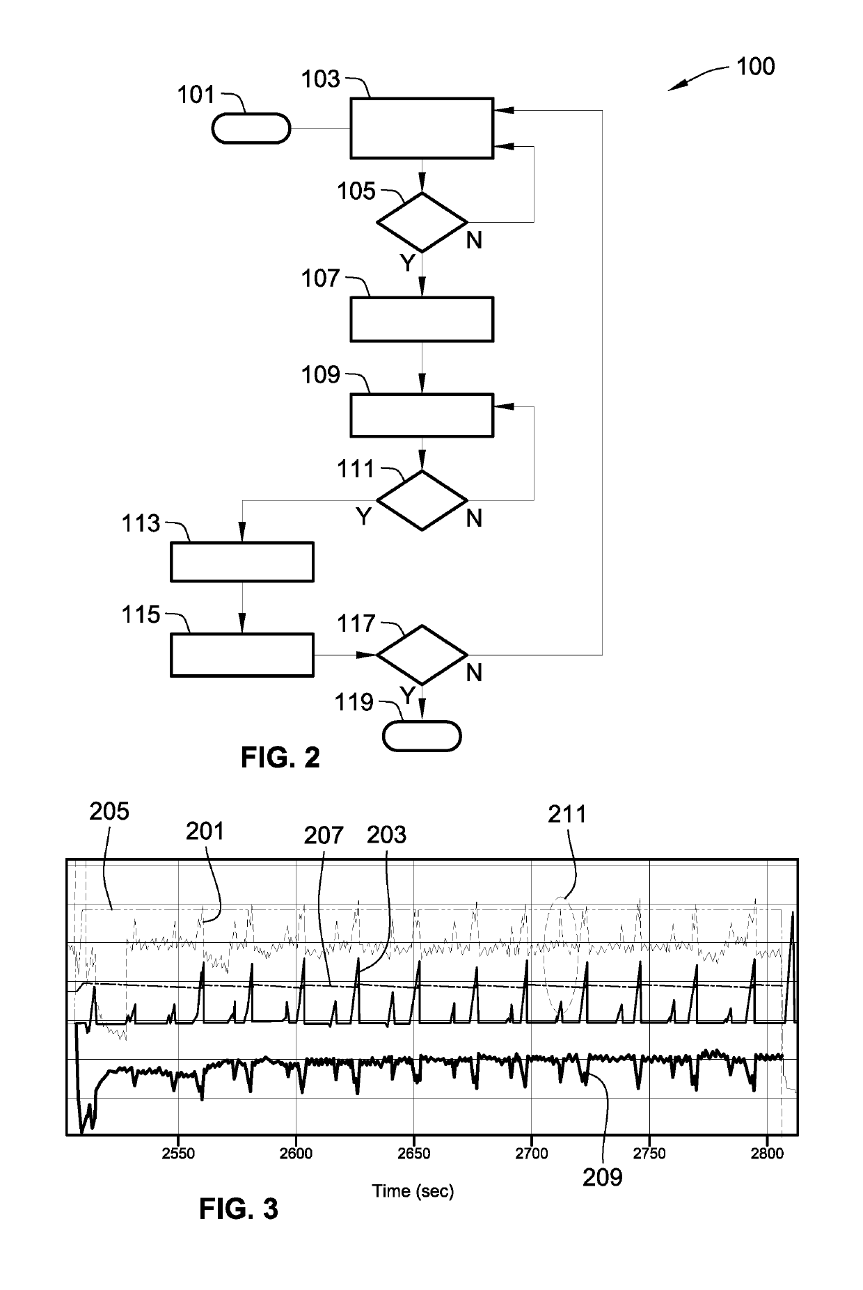
Disclosed are fuel cell architectures, fuel cell stack monitoring systems, and control logic for detecting fluid property changes in a fuel cell stack. A method is disclosed for detecting a flow property change of a fluid in a fuel cell system. This method includes determining, e.g., through system analysis or accessing a look-up table, a correlation between voltage change of the fuel cell system and flow property of the fluid, and determining, from the voltage-property correlation, a calibrated voltage drop corresponding to the property change of the fluid. The method monitors system voltage (e.g., moving average voltage of the fuel cell stack operating at steady state), and detecting a voltage magnitude change in the system voltage, e.g., when an anode exhaust valve is opened. Responsive to the voltage magnitude change being greater than the calibrated voltage drop, a signal is generated indicating detection of the flow property change.

Description

INTRODUCTION[0001]The present disclosure relates generally to fuel cell systems for converting gaseous hydrogen-based fuels into electricity. More specifically, aspects of this disclosure relate to monitoring systems and related control algorithms for characterizing fluid flow from the anode volume to the cathode volume of a fuel cell stack.[0002]Current production motor vehicles, such as the modern-day automobile, are originally equipped with a powertrain that operates to propel the vehicle and power the onboard vehicle electronics. The powertrain, which is inclusive of, and oftentimes misclassified as, a vehicle drivetrain, is generally comprised of a prime mover that delivers driving power to the vehicle's final drive system (e.g., differential, axle, and road wheels) through a multi-speed power transmission. Automobiles have generally been powered by a reciprocating-piston type internal combustion engine (ICE) because of its ready availability and relatively inexpensive cost, li...

Claims


Application Information

Patent Timeline
Patent Type & Authority Patents(United States)
IPC IPC(8): B60L9/00H01M8/04537H01M8/0438H01M8/04992H01M8/1018
CPCB60L50/72B60L58/32H01M8/04559H01M8/04402H01M8/04992H01M2250/402B60L2240/527H01M2008/1095H01M2250/20H01M8/0438B60L3/0053B60L2250/10B60L2260/44B60L58/30H01M8/04619H01M8/04753Y02E60/50Y02T90/40Y02B90/10
Inventor GAGLIARDO, JEFFREY J.DUBOIS, CHADWANG, XIAOFENGSINHA, MANISH
Owner GM GLOBAL TECH OPERATIONS LLC
Learn More