
Production method of sintered alloy, sintered-alloy compact, and sintered alloy

a production method and alloy technology, applied in metal-working apparatus, transportation and packaging, etc., can solve the problems of easy plastic deformation of the contact surface of sintered alloy, and reduced machinability of sintered alloy. , to achieve the effect of ensuring machinability

Active Publication Date: 2019-02-26
TOYOTA JIDOSHA KK +1
View PDF3 Cites 0 Cited by
  • Summary
  • Abstract
  • Description
  • Claims
  • Application Information

AI Technical Summary

Benefits of technology

The present patent provides a method for producing a sintered alloy that can secure machinability while suppressing adhesive wear. This is achieved by adding another kind of hard particles, specifically molybdenum, which helps to control plastic deformation of the iron-based base. The addition of these hard particles also allows for the formation of intermetallic compounds and molybdenum carbide, which further enhances the alloy's machinability. The resulting sintered alloy is thus more easily able to withstand adhesive wear during machining operations.

Problems solved by technology

Therefore, when the wear-resistant iron-based sintered alloy and a metal material of a sliding mating material that comes into contact therewith undergo metal-to-metal contact with each other, the contact surface of the sintered alloy is likely to be plastically deformed, and adhesive wear easily occurs on the contact surface.
On the other hand, there is concern that this may cause a reduction in the machinability of the sintered alloy.
Therefore, it is difficult to achieve both adhesive wear resistance and machinability.

Method used


Image

  • Production method of sintered alloy, sintered-alloy compact, and sintered alloy
  • Production method of sintered alloy, sintered-alloy compact, and sintered alloy
  • Production method of sintered alloy, sintered-alloy compact, and sintered alloy

Examples


example 1

ddition Amount of First Hard Particles

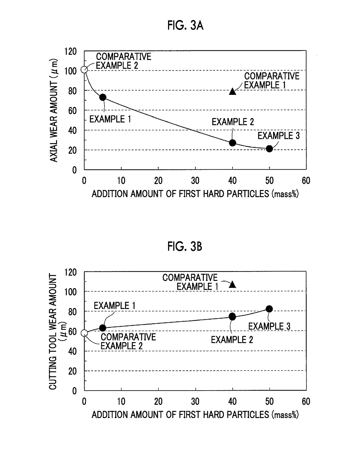
[0079]In a production method described below, a sintered alloy according to Example 1 was produced. As first hard particles, hard particles (manufactured by Daido Steel Co., Ltd) produced by a gas atomization method from an alloy containing Mo: 40 mass %, Ni: 30 mass %, Co: 20 mass %, Mn: 5 mass %, Si: 0.8 mass %, C: 1.2 mass %, and the remainder including Fe and unavoidable impurities (that is, Fe-40Mo-30Ni-20Co-5Mn-0.8Si-1.2C) were prepared. The first hard particles were classified to be in a range of 44 μm to 250 μm by using a sieve based on JIS Z 8801. In addition, the “grain size of particles” mentioned in the specification is a value classified in this method.

[0080]As second hard particles, second hard particles (manufactured by Kinsei Matec Co., Ltd.) produced by a grinding method from an Fe-65 alloy containing Mo: 65 mass % and the remainder including Fe and unavoidable impurities were prepared. The second hard particles were classified ...

examples 2 and 3

Amount of First Hard Particles

[0083]Specimens of sintered alloys were produced in the same manner as in Example 1. Examples 2 and 3 are examples for evaluating the optimal addition amount of the first hard particles. Examples 2 and 3 are different from Example 1 in that the first hard particles were added sequentially in proportions of 40 mass % and 50 mass % with respect to the total amount of the mixed powder as shown in Table 1.

example 4

[0084]A specimen of a sintered alloy was produced in the same manner as that in Example 2. Example 4 is an example in which Cr was added as a new element to the components of first hard particles. Example 4 is different from Example 2 in that hard particles produced by a gas atomization method from an alloy containing Mo: 34 mass %, Ni: 10 mass %, Co: 31 mass %, Cr: 3.7 mass %, Mn: 6 mass %, Si: 0.9 mass %, C: 1.0 mass %, and the remainder including Fe and unavoidable impurities (that is, Fe-34Mo-10Ni-31Co-3.7Cr-6Mn-0.9Si-1.0C) were used as the first hard particles.


PUM

PropertyMeasurementUnit
Temperatureaaaaaaaaaa
Percent by massaaaaaaaaaa

Abstract

A sintered alloy is produced from mixed powder containing first hard particles, second hard particles, graphite particles, and iron particles. The first hard particles are Fe—Mo—Ni—Co—Mn—Si—C-based alloy particles, the second hard particles are Fe—Mo—Si-based alloy particles, the mixed powder contains 5 to 50 mass % of the first hard particles, 1 to 8 mass % of the second hard particles, and 0.5 to 1.5 mass % of the graphite particles, when total mass of the first hard particles, the second hard particles, the graphite particles, and the iron particles is set as 100 mass %.

Description

INCORPORATION BY REFERENCE[0001]The disclosure of Japanese Patent Application No. 2016-011504 filed on Jan. 25, 2016 including the specification, drawings and abstract is incorporated herein by reference in its entirety.BACKGROUND[0002]1. Technical Field[0003]The present disclosure relates to a production method of a sintered alloy, a sintered-alloy compact, and a sintered alloy.[0004]2. Description of Related Art[0005]A sintered alloy containing iron as the base may be applied to a valve seat or the like of an internal combustion engine. In order to further improve wear resistance, hard particles may be included in a sintered alloy. In a case where hard particles are included, graphite particles and iron particles are mixed with the hard particles into a powder, and the mixed powder is compacted into a sintered-alloy compact. Thereafter, by heating the sintered-alloy compact and sintering the resultant, a sintered alloy is generally obtained.[0006]As a production method of such a s...

Claims


Application Information

Patent Timeline
IPC IPC(8): B22F3/10C22C38/04C22C38/10C22C38/12B22F1/00C22C38/02B22F1/05
CPCB22F3/10B22F1/0003B22F1/0011C22C38/02C22C38/10C22C38/105C22C38/12C22C38/04B22F2304/10B22F2301/35C22C33/0207B22F1/05B22F1/00C22C1/055C22C29/02C22C29/18C22C33/0292B22F2998/10B22F9/082B22F2009/0828B22F9/04B22F3/02
Inventor SHINOHARA, NOBUYUKIANDO, KIMIHIKOUEDA, YOSHIHISAYOSHIDA, YUSAKUSUGIMOTO, MASARU
Owner TOYOTA JIDOSHA KK
Learn More