
Powder forged member, powder mixture for powder forging, method for producing powder forged member, and fracture split type connecting rod using the same

a technology of powder mixture and forged parts, which is applied in the direction of connecting rod bearings, mechanical equipment, engine components, etc., can solve the problems of easy crack generation on forging, increase of process, and increase of product cost, so as to suppress the increase of hardness, increase content, and secure machinability

Inactive Publication Date: 2013-08-01
HONDA MOTOR CO LTD
View PDF1 Cites 0 Cited by
  • Summary
  • Abstract
  • Description
  • Claims
  • Application Information

AI Technical Summary

Benefits of technology

The solution improves fatigue strength while maintaining machinability and preventing cracks, ensuring self-consistency after fracture split and reducing tool abrasion, thus enhancing the productivity and cost-effectiveness of powder forged components.

Problems solved by technology

This causes a problem that the service life of a tool on machining after forging is remarkably reduced to unfortunately increase the product cost.
In addition, there is a disadvantage that the increased content of Cu causes the generation of cracks on forging easily.
However, the former method causes the increase of processes and the latter method uses expensive alloys, increasing the cost of the part and increasing the hardness of the part as in the method for increasing the content of C. This causes a disadvantage that the machinability is reduced.
The above conventional methods decrease the toughness of the part with the increase of the hardness, causing the fracture surface to tend to become flat.
When the part is produced using a fracture dividing method adopted in the connecting rod or the like, there is caused a particular problem of easily generating the positional shift of the part on assembling the part (i.e., reducing self-consistency).Patent Document 1: Japanese Unexamined Patent Publication No. 61-117203Patent Document 2: Japanese Unexamined Patent Publication No. 60-169501

Method used


Image

  • Powder forged member, powder mixture for powder forging, method for producing powder forged member, and fracture split type connecting rod using the same
  • Powder forged member, powder mixture for powder forging, method for producing powder forged member, and fracture split type connecting rod using the same
  • Powder forged member, powder mixture for powder forging, method for producing powder forged member, and fracture split type connecting rod using the same

Examples


example 1

Influence of Ratio of Free Cu

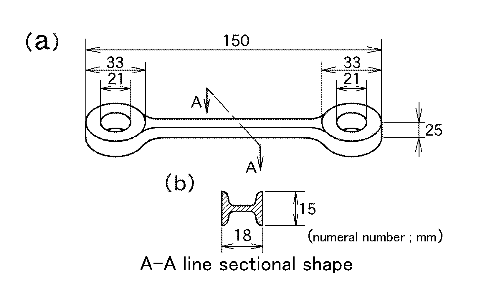
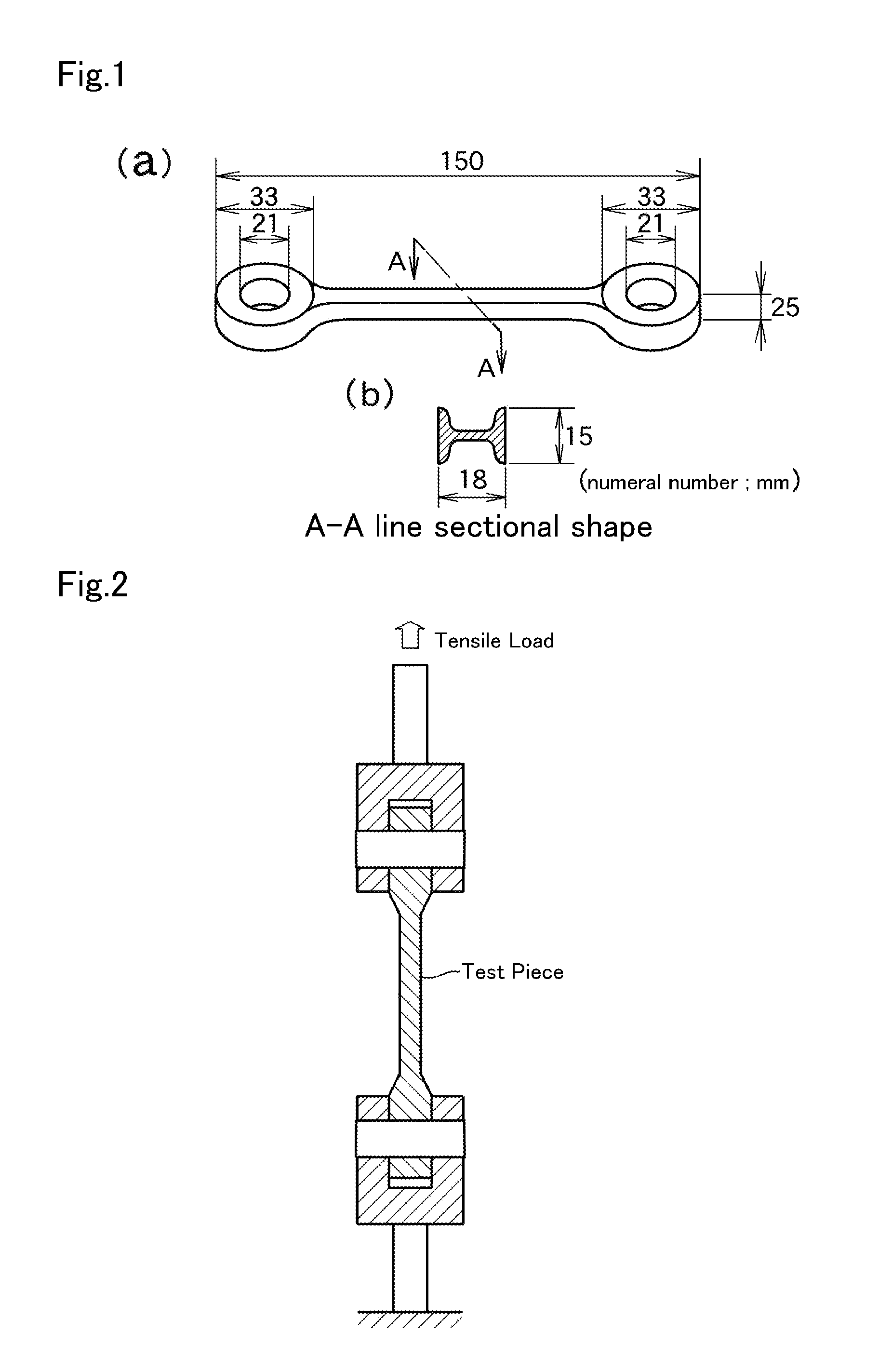
[0046]A graphite powder and a copper powder were added into a pure iron-based powder having a component composition shown in Table 1 so that the contents of C and Cu after being sintered were respectively 0.3% and 4%. Zinc stearate of 0.75% as a lubricant was further added thereto, and they were mixed for 30 minutes to produce a powder mixture. The powder mixture was subjected to preliminary compacting with a compacting surface pressure of 6 ton / cm2 to produce a compacted preform.

TABLE 1ComponentsCMnPSSiONContent (mass %)0.0010.190.010.0090.010.120.004

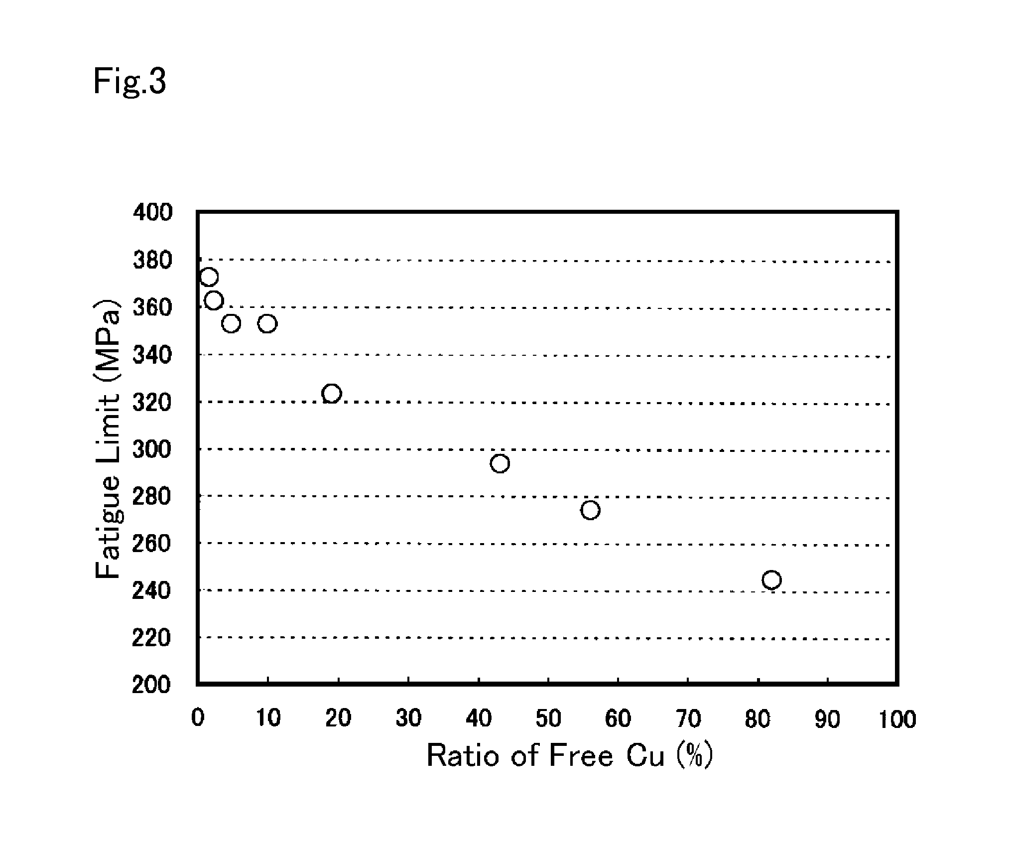
[0047]This compacted preform was dewaxed at 600° C. for 10 minutes under N2 gas atmosphere, and was then sintered at various temperatures of 1110 to 1260° C. for 10 minutes to produce a plurality of sintered preforms. The ratio of free Cu of each of some sintered preforms was measured by using the method described in the above [Composition of Powder Forged Member]. The remaining sintered preforms were immed...

example 2

Influence of Contents of C and Cu

[0050]A graphite powder and a copper powder were added into a pure iron-based powder having the same component composition as that of Example 1 shown in Table 1 with the addition amounts of the graphite powder and copper powder variously changed so that the content of C and Cu after being forged were respectively 0.1 to 0.6% and 2 to 5% to produce a powder mixture. The powder mixture was subjected to preliminary compacting in the same condition as that of Example 1 described above to form a compacted preform. This compacted preform was dewaxed at 600° C. for 10 minutes under N2 gas atmosphere, and was then sintered at 1120° C. for 30 minutes under N2 gas atmosphere to produce sintered preforms. The sintered preforms were heated at 1050° C. for 30 minutes under N2 gas atmosphere, and was then forged with a forging pressure of 10 ton / cm2 to produce test pieces of powder forged members imitating the shape of the same connecting rod as that of Example 1 ...

example 3

Influence of Relative Density

[0056]Next, there were produced test pieces of powder forged members having the same component composition (C: 0.3%, Cu: 3.5%) as that of test piece No. 218 of Example 2 in the same condition as that of Example 2 except that only a forging pressure was variously changed in the range of 2.5 to 10 ton / cm2. The influence of the relative density of the powder forged member exerted on the fatigue limit was investigated. While the fatigue limit was measured, the HRB hardness of each of the test pieces was also measured. Table 4 shows test results.

TABLE 4TestForgingRelativepiecespressuredensityHardnessFatigue limitNo.(ton / cm2)(%)(HRB)(MPa)2181099105.03463017.598100.03383029.599101.53403036.09797.03293044.09591.53163053.59486.52993062.59380.0286

[0057]As shown in above Table 4, it is confirmed that the fatigue limit of 325 MPa or more could be ensured when the relative density to the theoretical density was 97% or more.


PUM

PropertyMeasurementUnit
fatigue strengthaaaaaaaaaa
elongationaaaaaaaaaa
temperatureaaaaaaaaaa

Abstract

A member produced by powder forging which retains machinability and improved fatigue strength without having an increased hardness and can retain self conformability after fracture splitting; a powder mixture for powder forging; a process for producing a member by powder forging; and a fracture splitting connecting rod obtained from the member produced by powder forging. The member produced by powder forging is one obtained by preforming a powder mixture, subsequently sintering the preform, and forging the resultant sintered preform at a high temperature. The free-copper proportion in the sintered preform at the time when the forging is started is 10% or lower, and the member obtained through the forging has a composition containing, in terms of mass %, 0.2-0.4% C, 3-5% Cu, and up to 0.4% Mn (excluding 0), the remainder being iron and incidental impurities, and has a ferrite content of 40-90%.

Description

CROSS-REFERENCE TO RELATED APPLICATIONS[0001]This is a divisional application of U.S. patent application Ser. No. 13 / 307,662, filed on Jul. 2, 2009, which is a 371 of International Application No. PCT / JP2007 / 063377, filed on Jul. 4, 2007, which claims the benefit of priority from the prior Japanese Patent Application No. 2006-186927 filed on Jul. 6, 2006, the entire contents of which are incorporated herein by references.TECHNICAL FIELD[0002]The present invention relates to a powder forged member obtained by subjecting a powder mixture to preliminary compacting, then sintering the subjected compacted preform, and thereafter forging the obtained sintered preform, a powder mixture for powder forging, a method for producing the powder forged member, and a fracture split type connecting rod produced using the powder forged member.BACKGROUND ART[0003]Conventionally, there has been widely carried out a powder forging method for subjecting a powder mixture to preliminary compacting, then s...

Claims


Application Information

Patent Timeline
Patent Type & Authority Applications(United States)
IPC IPC(8): F16C7/02B22F3/17
CPCB21J5/002B21K1/766B22F2998/10C22C33/0264C22C38/04Y10T74/2142C22C38/16F16C7/02B22F3/17B22F3/10F16C7/023F16C9/045C22C33/02B21J5/00B21K1/14B22F1/00B21K1/76B22F3/16B22F3/24
Inventor SATO, MASAAKITAKADA, MINORUTAKADA, KENTAROIIDA, ZENJIKOGURE, RYOSUKE
Owner HONDA MOTOR CO LTD
Learn More