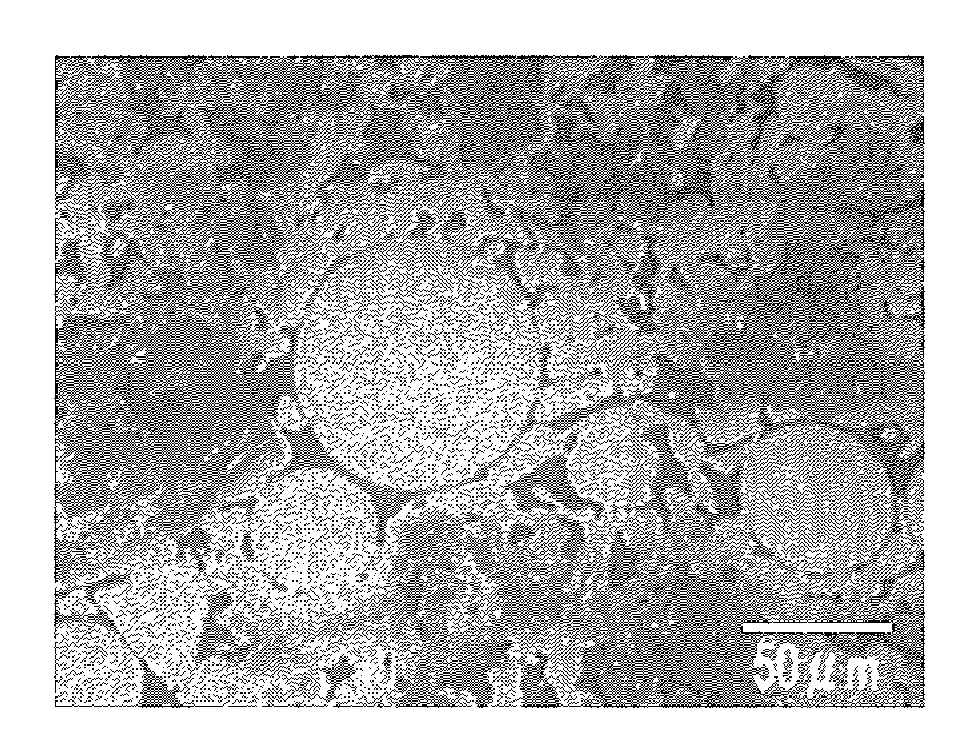
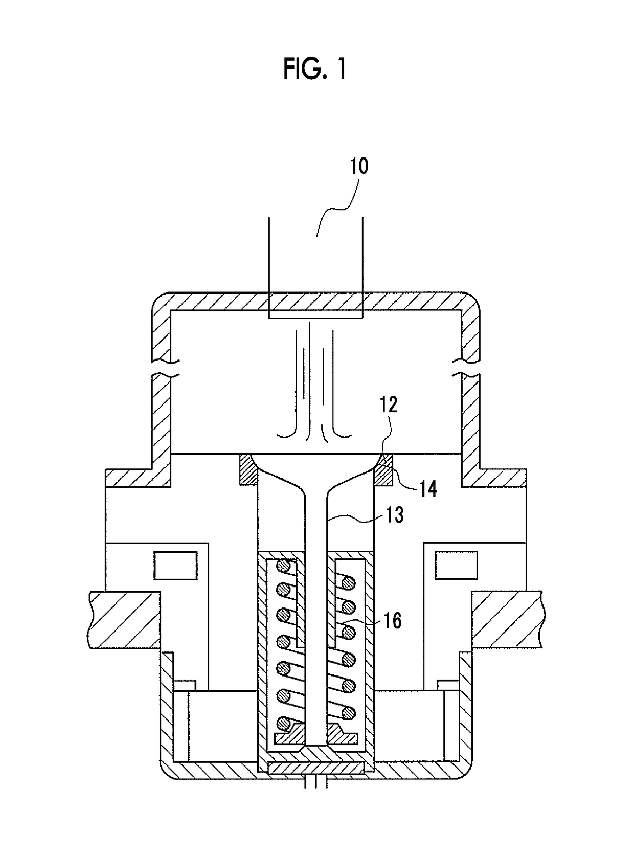
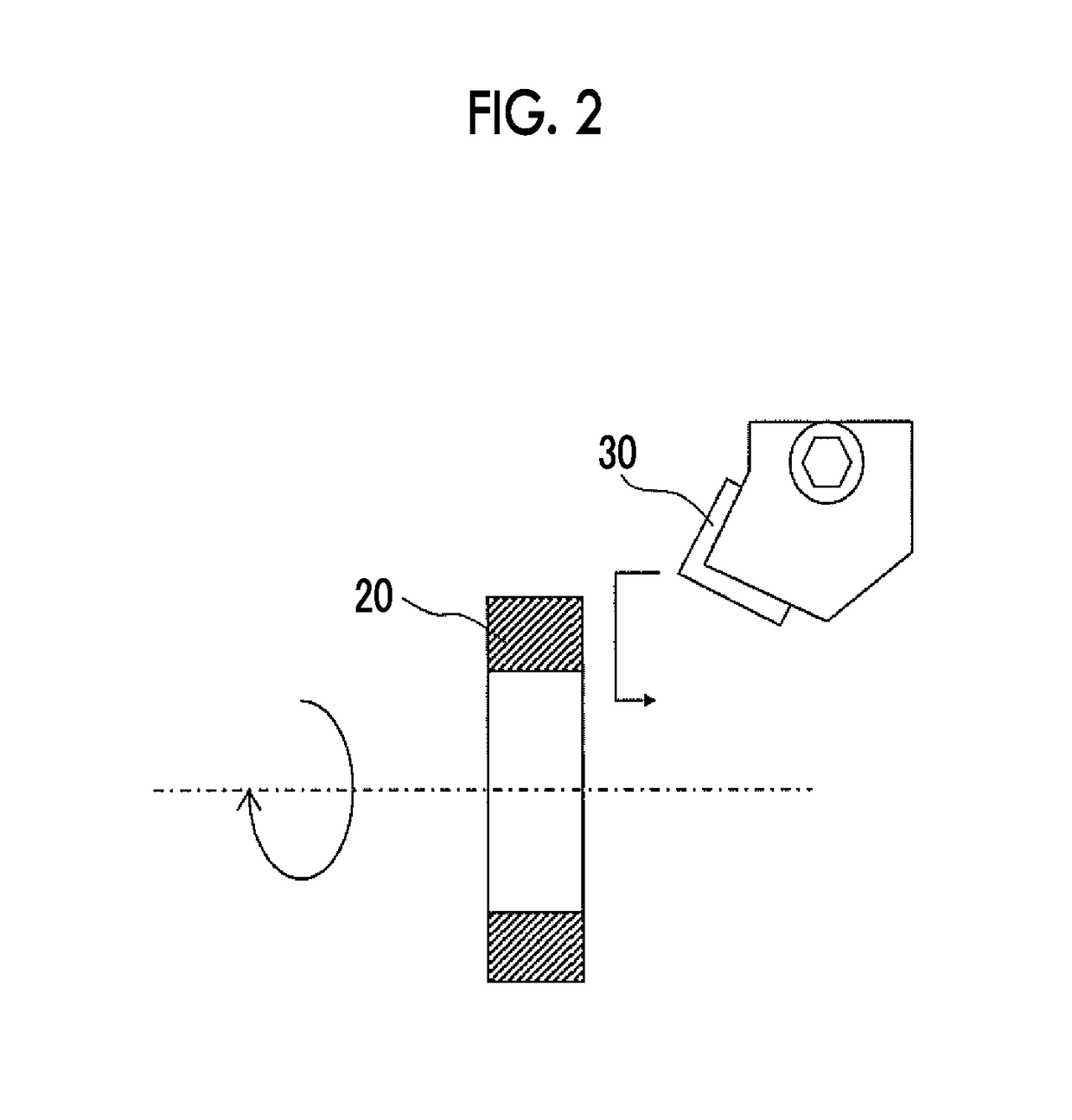

Manufacturing method of sintered alloy, compact for sintering, and sintered alloy

a manufacturing method and alloy technology, applied in the field of manufacturing methods of sintered alloys, can solve the problems of reduced machinability, difficult balance between adhesive wear resistance and machinability, and achieve the effect of ensuring the machinability of sintered alloys

Active Publication Date: 2018-04-24
TOYOTA JIDOSHA KK +2
View PDF4 Cites 0 Cited by
  • Summary
  • Abstract
  • Description
  • Claims
  • Application Information

AI Technical Summary

Benefits of technology

[0008]However, a matrix material that binds the hard particles in the sintered alloy, which is manufactured by the manufacturing method described in JP 2004-156101 A, is a Fe—C system based material, in which C in the graphite particles are diffused into the iron particles, and is thus soft. Accordingly, when the sintered alloy contacts a metallic material in a mated sliding member, plastic deformation of a contact surface of the sintered alloy is facilitated, and adhesive wear of this contact surface is facilitated. In order to avoid these, hardness of the sintered alloy is desirably increased. However, the increased hardness of the sintered alloy results in decreased machinability. Therefore, it is difficult to balance adhesive wear resistance and the machinability.
[0009]The disclosure provides a manufacturing method of a sintered alloy, a sintered-alloy compact, and a sintered alloy capable of securing machinability while suppressing adhesive wear.
[0010]The inventors have considered that the adhesive wear of the contact surface is promoted by the plastic deformation of the iron-based matrix of the sintered alloy, as described above. From such a perspective, the inventors have examined to add another type of hard particles that can suppress the plastic deformation of the iron-based matrix in addition to the conventional hard particles that suppress the abrasive wear. For this reason, the inventors have focused their attention on molybdenum as a main component of the hard particles and reached such a finding that the plastic deformation of the iron-based matrix can be controlled by scattering iron-molybdenum intermetallic compounds and molybdenum carbides precipitated during sintering in the iron-based matrix.
[0013]According to the disclosure, machinability of the sintered alloy can be secured while adhesive wear thereof is suppressed.

Problems solved by technology

However, the increased hardness of the sintered alloy results in decreased machinability.
Therefore, it is difficult to balance adhesive wear resistance and the machinability.

Method used


Image

  • Manufacturing method of sintered alloy, compact for sintering, and sintered alloy
  • Manufacturing method of sintered alloy, compact for sintering, and sintered alloy
  • Manufacturing method of sintered alloy, compact for sintering, and sintered alloy

Examples


example 1

[0088]A sintered alloy according to Example 1 was manufactured by the following manufacturing method. As the first hard particles, hard particles (manufactured by Sanyo Special Steel Co., Ltd.) were prepared. The hard particles were produced from an alloy that contained 30 mass % of Mo, 5 mass % of Cr, 6 mass % of Mn, and the remainder formed with Fe and inevitable impurities (that is, Fe-30Mo-5Cr-6Mn) by a gas atomizing method. A sieve that complies with JIS Standard Z8801 was used to classify the first hard particles into a range of 44 μm to 250 μm. Note that values classified by this method are used as “the particle size (the particle diameter) of the particle” in this specification.

[0089]As the second hard particles, second hard particles (manufactured by KINSEI MATEC CO., LTD.) were prepared. The second hard particles were produced from a Fe-65Mo-1Si alloy that contains 65 mass % of Mo, 1 mass % of Si, and the remainder formed with Fe and inevitable impurities by a grinding met...

examples 2 , 3

Examples 2, 3

[0092]Test pieces of the sintered alloy were produced in the same manner as Example 1. As shown in Table 1, Example 2 differs from Example 1 in such a way that the composition of the first hard particles was Fe-30Mo-10Cr-6Mn (Cr was increased to occupy 10 mass %).

[0093]As shown in Table 1, Example 3 differs from Example 1 in such a way that the composition of the first hard particles was Fe-35Mo-10Cr-6Mn (Mo was increased to occupy 35 mass %, and Cr was increased to occupy 10 mass %).

examples 4 to 7

tive Amount of the First Hard Particles

Test pieces of the sintered alloy were produced in the same manner as Example 1. Examples 4 to 7 are examples that were implemented to evaluate an optimum additive amount of the first hard particles.

[0109]As shown in Table 2, Example 4 differs from Example 1 in such a way that the first hard particles occupying 5 mass % of the entire mixed powder were added. A test piece of the sintered alloy in Example 5 was the same as that in Example 1.

[0110]As shown in Table 2, Example 6 differs from Example 1 in points that the first hard particles occupying 40 mass % of the entire mixed powder were added and that the composition of the first hard particles was Fe-25Mo-5Cr-6Mn (Mo was reduced to occupy 25 mass %).

[0111]As shown in Table 2, Example 7 differs from Example 1 in points that the first hard particles occupying 50 mass % of the entire mixed powder were added and that the composition of the first hard particles was Fe-30Mo-10Cr-6Mn (Cr was increas...


PUM

PropertyMeasurementUnit
particle diameteraaaaaaaaaa
mass %aaaaaaaaaa
mass %aaaaaaaaaa

Abstract

Mixed powder that contains first hard particles, second hard particles, graphite particles, and iron particles is used to manufacture a sintered alloy. The first hard particle is a Fe—Mo—Cr—Mn based alloy particle, the second hard particle is a Fe—Mo—Si based alloy particle. The mixed powder contains 5 to 50 mass % of the first hard particles, 1 to 8 mass % of the second hard particles, and 0.5 to 1.0 mass % of the graphite particles when total mass of the first hard particles, the second hard particles, the graphite particles, and the iron particles is set as 100 mass %.

Description

INCORPORATION BY REFERENCE[0001]The disclosure of Japanese Patent Application No. 2016-019963 filed on Feb. 4, 2016 including the specification, drawings and abstract is incorporated herein by reference in its entirety.BACKGROUND[0002]1. Technical Field[0003]The disclosure relates to a manufacturing method of a sintered alloy, a sintered-alloy compact, and a sintered alloy.[0004]2. Description of Related Art[0005]There is a case where a sintered alloy with an iron matrix is used for a valve seat and the like of an internal combustion engine. There is also a case where hard particles are contained in a sintered alloy to improve wear resistance. In the case where the hard particles are contained, graphite particles and iron particles are mixed with the hard particles into a powder form and press the mixed powder into a sintered-alloy compact. Thereafter, the sintered-alloy compact is heated and sintered into a sintered alloy.[0006]As a manufacturing method of such a sintered alloy, a ...

Claims


Application Information

Patent Timeline
Patent Type & Authority Patents(United States)
IPC IPC(8): B22F7/00C22C29/02C22C38/00C22C1/10C22C45/10C22C45/02C22C30/00C22C38/12C22C38/44C22C1/05C22C1/04C22C27/06B32B15/01B32B15/18C22C38/22C22C38/02C22C38/04C22C27/04B22F3/16C22C38/38B22F1/12
CPCB22F7/008B32B15/01B32B15/18C22C1/04C22C1/05C22C1/051C22C1/053C22C1/055C22C1/10C22C27/04C22C27/06C22C29/02C22C30/00C22C38/00C22C38/02C22C38/04C22C38/12C22C38/22C22C38/38C22C38/44C22C45/02C22C45/10B22F3/16Y10T428/12979B22F2301/35B22F2302/40B22F2304/10B22F2998/10Y10T428/1209Y10T428/12028Y10T428/12042Y10T428/12056Y10T428/12125Y10T428/12132Y10T428/12139Y10T428/12146Y10T428/12153Y10T428/12229Y10T428/12479Y10T428/12951Y10T428/12958Y10T428/12972B22F3/02B22F3/10C22C33/0207C22C33/0278B22F1/09B22F1/12B22F3/1039C22C33/0285B22F2999/00B22F5/106C22C1/058C22C1/045
Inventor SHINOHARA, NOBUYUKIANDO, KIMIHIKOUEDA, YOSHIHISAYOSHIDA, YUSAKUSUGIMOTO, MASARUSAWADA, TOSHIYUKIFUKUMOTO, SHINGO
Owner TOYOTA JIDOSHA KK
Learn More