Virtual mid-bus generation in a power system for industrial control

Active Publication Date: 2018-12-25
ROCKWELL AUTOMATION TECH
View PDF1 Cites 10 Cited by
  • Summary
  • Abstract
  • Description
  • Claims
  • Application Information

AI Technical Summary

Benefits of technology

The patent describes a way to use half-bridge inverters in linear motor track sections to efficiently connect a common point of all drive coils to a full-bus DC power rail and a DC reference, allowing for bi-directional flow of a sum of currents of all drive coils. Separate upper and lower drive switches can be controlled to synchronize their PWM cycles and duty cycle commands with respect to a virtual mid-bus, resulting in a desired voltage across the drive coils and propel a mover. This approach reduces the need for full-bridge inverters for each drive coil, saving space and cost.

Problems solved by technology

Linear motor drive systems frequently use “half-bridge” inverters comprised of upper and lower switches to produce current in the drive coils which results in a propulsive force on the movers.
However, half-bridge inverters often produce significant ripple current, regardless of the level of commanded current.
Such ripple current provides no useful work in the system and causes excess heat and energy loss.
Such power supplies can be cumbersome to produce and expensive.

Method used


Image

  • Virtual mid-bus generation in a power system for industrial control
  • Virtual mid-bus generation in a power system for industrial control
  • Virtual mid-bus generation in a power system for industrial control

Examples


Embodiment Construction

[0024]The various features and advantageous details of the subject matter disclosed herein are explained more fully with reference to the non-limiting embodiments described in detail in the following description.

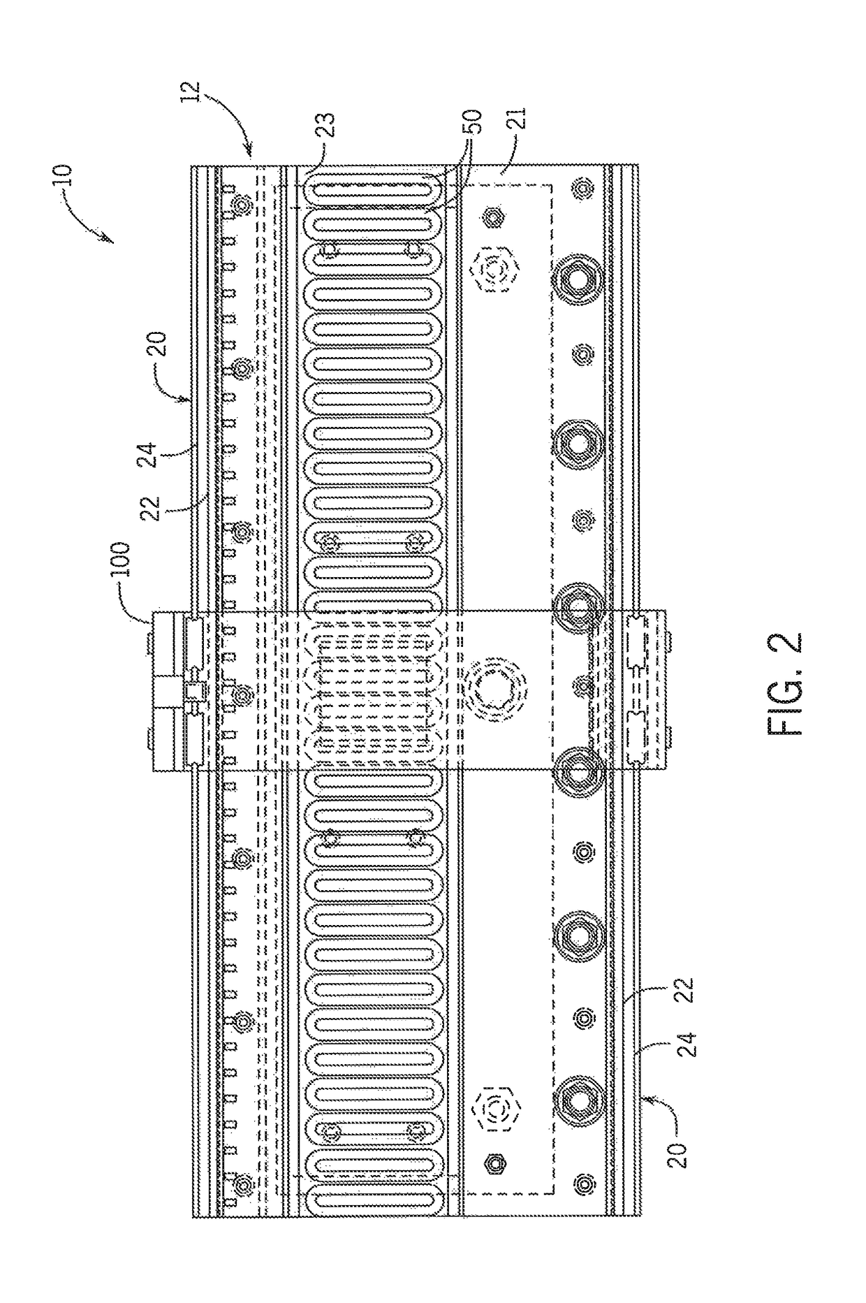
[0025]Turning initially to FIG. 1, an exemplary transport system for moving articles or products includes a track 10 made up of multiple segments 12 or sections, such as segments 12a, 12b, 12c and so forth. According to the illustrated embodiment, the segments 12 define a generally closed loop supporting a set of movers 100 movable along the track 10. The track 10 is oriented in a horizontal plane and supported above the ground by a base 15 extending vertically downward from the track 10. According to the illustrated embodiment, the base 15 includes a pair of generally planar support plates 17, located on opposite sides of the track 10, with mounting feet 19 on each support plate 17 to secure the track 10 to a surface. The illustrated track 10 includes four straight segments...


PUM


Abstract

A half-bridge inverter comprised of upper and lower switches can be placed in linear motor track sections to alternately connect a common point of all drive coils to a full-bus DC power rail (“full-bus”) and a DC reference, according to PWM command signals, functioning as a “virtual mid-bus” to allow bi-directional flow of a sum of currents of all drive coils in the section. Separate upper and lower drive switches of the half-bridge inverters that are also connected to drive the drive coils can then be controlled, according to separate PWM command signals, to synchronize their PWM cycles and duty cycle commands with respect to the virtual mid-bus at times when a mover is not present, resulting in zero voltage across the drive coils, or command different duty cycles with respect to the virtual mid-bus when a mover is present, resulting in a desired voltage across the drive coils. The desired voltage can produce a current in the drive coils to electromagnetically propel the mover.

Description

BACKGROUND INFORMATION[0001]The present invention relates to motion control systems and, more specifically, to motion control systems including a track segment for linear motor drive systems supporting movers on tracks in which upper and lower mid-bus generation switches disposed in such track segments can receive Pulse Width Modulated (PWM) command signals for producing a virtual mid-bus to a common side of drive coils in the track segment which, in turn, can allow such drive coils to be used to electromagnetically propel movers along the track.[0002]Motion control systems utilizing movers and linear motors can be used in a wide variety of processes (e.g. packaging, manufacturing, and machining) and can provide an advantage over conventional conveyor belt systems with enhanced flexibility, extremely high speed movement, and mechanical simplicity. The motion control system includes a set of independently controlled “movers” each supported on a track for motion along the track. The t...

Claims


Application Information

Patent Timeline
IPC IPC(8): H02K41/00H02P1/00H02P3/00H02P5/00H02P7/025H02M7/5395B65G54/02H02M3/155H02K41/035
CPCH02P7/025H02M7/5395B65G54/02H02M3/155H02K41/0358H02K41/031H02P25/064H02J1/02H02M3/1555
Inventor OZIMEK, PATRICK E.
Owner ROCKWELL AUTOMATION TECH
Why Eureka
Try Eureka