
Sliding member

a sliding member and member technology, applied in the direction of shafts and bearings, rotary machine parts, bearings, etc., can solve the problems of unable to maintain the desired sliding property, and achieve the effect of suppressing adhesion and corrosion of the sliding member, excellent cavitation-erosion resistance properties, and high hardness properties

Active Publication Date: 2018-12-04
SENJU METAL IND CO LTD
View PDF35 Cites 1 Cited by
  • Summary
  • Abstract
  • Description
  • Claims
  • Application Information

AI Technical Summary

Benefits of technology

The present invention provides a sliding member that has hardness and abrasion resistance properties suitable for heavy load applications. By using a shot blasting treatment on the surface of the object, the hardness of the sliding surface can be improved. The sliding member also has a specific surface roughness that can form an oil reservoir, preventing adhesion and corrosion. These technical features make the sliding member ideal for use in hydraulic equipment and other fields where resistance to cavitation and erosion is important.

Problems solved by technology

However, under a circumstance of hydraulic equipment and the like to which heavy load is applied, there may be a case that cannot keep an uneven shape formed by the shot-blasting treatment depending on hardness of the sliding surface, thereby disabling maintenance of desired sliding property.

Method used


Image

  • Sliding member
  • Sliding member
  • Sliding member

Examples


Embodiment Construction

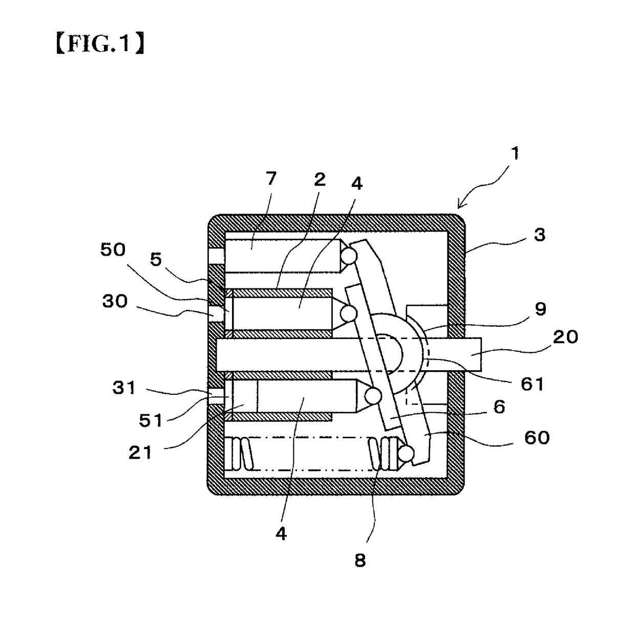
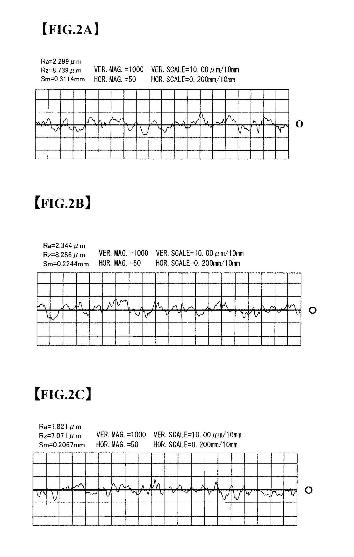
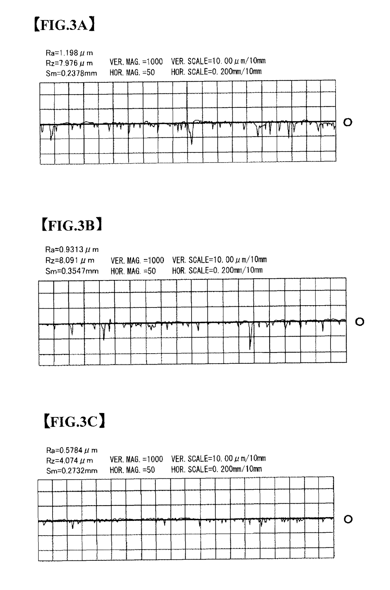
[0052]In an sliding member of the present invention, a sliding surface is formed on a surface of a sliding layer to which a shot-blasting treatment is performed, the surface of the shot-blasted sliding layer having an uneven shape exhibiting arithmetic average roughness (Ra) of more than 0 μm but 2.0 μm or less, ten-point average roughness (Rz) of more than 0 μm but 7.5 μm or less and surface hardness (Hv) of 150-250 and the sliding surface slidably supporting an object to be slid. In the sliding member, the sliding surface having a predetermined surface roughness is formed by, for example, rubbing together the surface of the sliding layer and a surface to be slid of an object to be slid after the shot-blasting treatment is performed on the surface of the sliding member. The sliding member is paired with the object to be slid.

[0053]In the sliding member of the subject embodiment, the sliding layer is formed with a metal material of a single composition, an alloy material of a predet...


PUM

PropertyMeasurementUnit
average roughnessaaaaaaaaaa

Abstract

A sliding member which has a hardness suitable for use under heavy-load conditions and which exhibits excellent abrasion resistance property. A sliding surface is formed on a surface of a sliding layer that slidably supports an object to be slid. The sliding surface is then shot-blasted and is formed to have an uneven shape exhibiting an arithmetic average roughness (Ra) of more than 0 to 2.0 μm, a ten-point average roughness (Rz) of more than 0 to 7.5 μm, and a surface hardness (Hv) of 150 to 250.

Description

CROSS-REFERENCE TO RELATED APPLICATIONS[0001]This application is the United States national phase of International Application No. PCT / JP2014 / 075477 filed Sep. 25, 2014, and claims priority to Japanese Patent Application No. 2013-202304 filed Sep. 27, 2013, the disclosures of which are hereby incorporated in their entirety by reference.TECHNICAL FIELD[0002]The present invention relates to a sliding member that slidably supports an object to be slid.BACKGROUND[0003]In general, it is preferable that a sliding surface has a smooth surface to reduce friction in the sliding surface. However, if the sliding surface is the smooth surface, a friction resistance can be lower but some level of heat is generated at the sliding surface so that there is a possibility that an adhesion occurs in accordance with so-called seizing. Therefore, it is required that the sliding surface has any proper surface roughness.[0004]In the past, forming a concave portion by applying shot-blasting to the sliding ...

Claims


Application Information

Patent Timeline
Patent Type & Authority Patents(United States)
IPC IPC(8): F16C33/10F16C33/06F16C33/12F16C33/14
CPCF16C33/10F16C33/06F16C33/103F16C33/12F16C33/14F16C2202/04F16C2360/42F16C2204/12F16C2223/08F16C2240/40F16C2240/48F16C2240/54F16C2240/60F16C2204/10
Inventor SATO, NAOKIKURATA, RYOICHI
Owner SENJU METAL IND CO LTD
Learn More