
Method and apparatus for simultaneous controlling of fuel concentration and temperature of liquid fuel by sensor-less and temperature-control based feed-back control, liquid fuel cell apparatus using the same

a technology of liquid fuel and temperature control, which is applied in the direction of fuel cells, electrical appliances, electrochemical generators, etc., can solve the problems of reducing the energy efficiency of fuel, reducing the performance, and deteriorating the performance of the fuel cell, so as to reduce the power consumed for operation and reduce the price of the apparatus. , the effect of simple and small design

Active Publication Date: 2018-09-18
KOREA INST OF SCI & TECH
View PDF20 Cites 0 Cited by
  • Summary
  • Abstract
  • Description
  • Claims
  • Application Information

AI Technical Summary

Benefits of technology

[0067]According to embodiments of the present disclosure, in an aspect, the fuel cell apparatus of the present disclosure is basically a sensor-less type not using a concentration sensor. Therefore, the fuel cell apparatus may have a simple and small design, which reduces the power consumed for operation and lowers the apparatus price.
[0069]According to embodiments of the present disclosure, in another aspect, in comparison to an existing sensor-less concentration control method, the fuel cell apparatus ensures a smaller error, a more stable operation, an excellent response characteristic, easy temperature control of the stack, and a long life span.
[0070]According to embodiments of the present disclosure, in another aspect, since a concentration of the fuel supplied to the stack and a temperature of a mixture solution circulating in the fuel circulation system are simultaneously controlled based on the amount of fuel consumed by the fuel cell system and the temperature of the stack, it is possible to maximize the efficiency of the fuel cell system while constantly maintaining the concentration of the fuel injected into the fuel cell and the temperature of the stack.
[0071]According to embodiments of the present disclosure, in another aspect, since a heat removal rate of the heat exchanger is controlled in a feed-back manner by comparing a present temperature of the stack with the target temperature, the temperature of the mixed solution circulating in the fuel circulation system may be controlled to minimize a heat loss of the stack, which may occur due to the change of the ambient temperature, and loss of water circulating in the fuel circulation system.

Problems solved by technology

In other words, when a liquid fuel used in the liquid fuel cell is supplied with a high concentration, a crossover phenomenon may occur so that the liquid fuel moves from the anode to the cathode through the electrolyte membrane, and to this end the fuel crossover may cause various problems such as a performance deterioration of the fuel cell, a decrease in energy efficiency of the fuel, etc.
If the fuel concentration is higher than an optimal fuel concentration of the fuel cell, the amount of fuel crossover from the anode to the cathode through the electrolyte membrane may increase, which in turn may lower the performance.
To the contrary, if a fuel with a low concentration is supplied to the anode of the fuel cell stack, a fuel deficiency may occur at the anode, which may decrease performance of the fuel cell.
Meanwhile, if a fuel is stored or used in a diluted state inside the liquid fuel cell apparatus, or if a fuel which has been used once and is still containing an unreacted fuel is discharged out and wasted, the energy efficiency of the fuel cell apparatus deteriorates and the advantage as a portable high-density power source may be lost.
For this reason, the conventional concentration control method makes the fuel cell system more complicated and bigger, and the parasitic power losses due to the corresponding sensor and the pump increases, which deteriorate the energy efficiency of the fuel cell system.
Further, concentration sensors presently available in the art are expensive and have great measurement errors and short life spans.
Therefore, if the concentration sensors are applied to the fuel cell system, the fuel cell system has an increased production cost and lower safety, and therefore may not maintain price and quality competitiveness as a portable power source.
However, as time goes on, the reproducibility and stability of measurement is lowered since the catalyst in the sensor loses its activity.
However, according to an observation by the inventors of the present disclosure, this method takes much time to increase a concentration to a target concentration since it does not use a feed-back function and a concentration control method for a startup of a liquid fuel cell in combination.
In addition, the rate of change of diluted fuel concentration is slow, and the ability to react to a change of outside environments is not provided.
However, according to an observation by the inventors of the present disclosure, this method has a slow response due to a delay time for periodic observing, does not ensure accurate concentration control, and has an increased error in concentration control if the performance of the fuel cell deteriorates over time due to a long-term operation.
However, according to an observation by the inventors of the present disclosure, this method also takes relatively long time for controlling a concentration and operating a fuel cell in a normal state, and a temperature and a voltage of the fuel cell stack and a concentration of the fuel continuously vary.
In addition, when the performance of the fuel cell deteriorates over time, the concentration control error increases.
Further, while the above methods control a fuel concentration in a normal state operation of a liquid fuel cell without using a sensor, a method of controlling a fuel concentration in a startup of a liquid fuel cell or controlling an output current density is not being developed.
However, according to an observation by the inventors of the present disclosure, this method controls only a fuel concentration in the startup period, and a method for controlling an output current density in the period is not proposed.
In addition, since a concentration sensor is used, this method is fundamentally different from a concentration control method not using a sensor, and the variation of ambient temperature which may occur in operation is not considered.
If the ambient temperature increases in operation, a water shortage phenomenon in which water in the water tank is exhausted may occur.
If the ambient temperature decreases on the contrary, the heat loss of the stack may increase, which reduces the efficiency of the fuel and the system.
Therefore, the fuel cell apparatus may have a simple and small design, which reduces the power consumed for operation and lowers the apparatus price.

Method used


Image

  • Method and apparatus for simultaneous controlling of fuel concentration and temperature of liquid fuel by sensor-less and temperature-control based feed-back control, liquid fuel cell apparatus using the same
  • Method and apparatus for simultaneous controlling of fuel concentration and temperature of liquid fuel by sensor-less and temperature-control based feed-back control, liquid fuel cell apparatus using the same
  • Method and apparatus for simultaneous controlling of fuel concentration and temperature of liquid fuel by sensor-less and temperature-control based feed-back control, liquid fuel cell apparatus using the same

Examples


Embodiment Construction

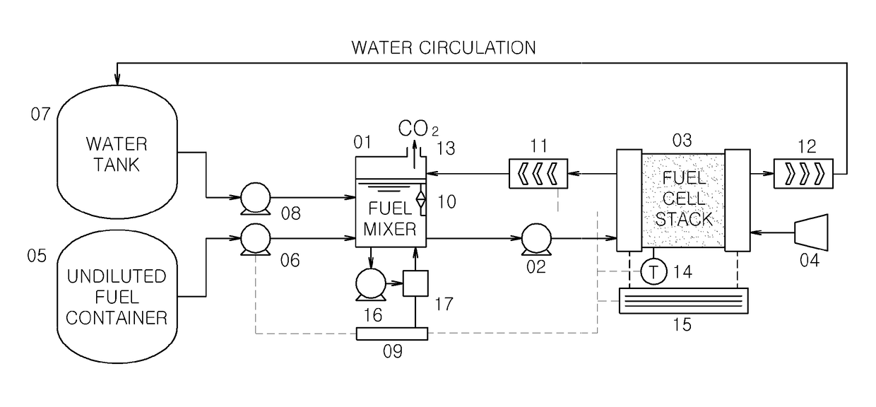
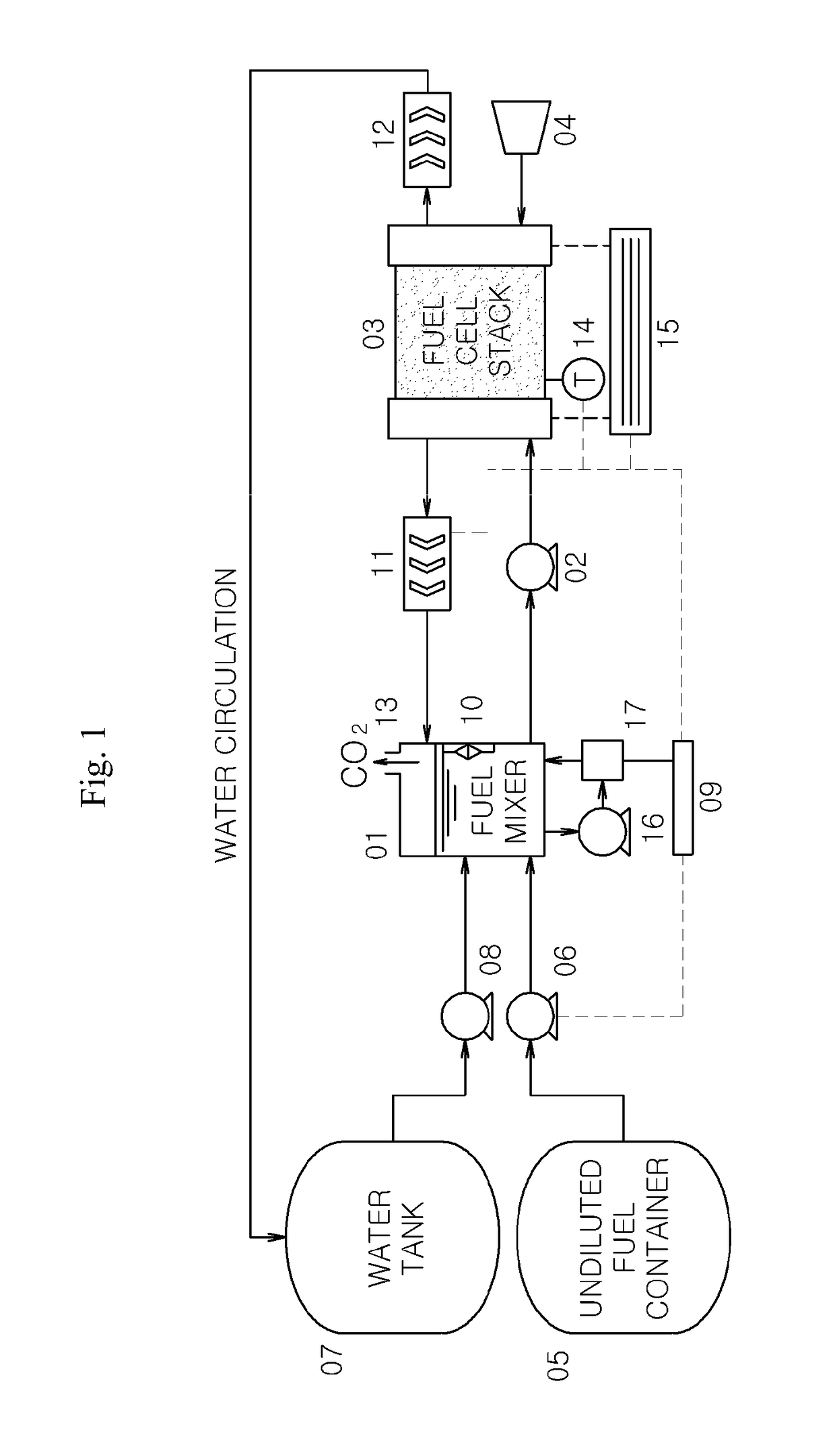
[0090]1: fuel mixer[0091]2: diluted fuel supply pump[0092]3: fuel cell stack[0093]4: air blowing fan[0094]5: undiluted fuel container[0095]6: undiluted fuel supply pump[0096]7: water tank[0097]8: water supply pump[0098]9: concentration controller using a concentration sensor[0099]10: liquid level meter[0100]11: anode heat exchanger[0101]12: cathode heat exchanger[0102]13: carbon dioxide gas discharger[0103]14: temperature measuring device[0104]15: output voltage / current measurement device[0105]16: sensor pump (for supplying a diluted fuel to a concentration sensor)[0106]17: methanol concentration sensor[0107]18: control device of a liquid fuel cell not using a concentration sensor

DETAILED DESCRIPTION

[0108]Example embodiments now will be described more fully hereinafter with reference to the accompanying drawings, in which example embodiments are shown. The present disclosure may, however, be embodied in many different forms and should not be construed as limited to the example embod...


PUM

PropertyMeasurementUnit
temperatureaaaaaaaaaa
output current densityaaaaaaaaaa

Abstract

A concentration of a fuel supplied to a fuel cell and a heat exchange rate of a heat exchanger are controlled simultaneously in order to maintain a temperature of fuel cell stack and a diluted fuel concentration that is supplied to the fuel cell stack in a target level. Further, by appropriately responding to an exterior temperature changes or unexpected fuel cell performance changes, it is possible to improve a system efficiency and stability of fuel cell operation and to regulate the fuel concentration quickly and accurately compared to a prior sensor-less concentration controller.

Description

CROSS-REFERENCE TO RELATED APPLICATION[0001]This application claims priorities to Korean Patent Application No. 10-2012-0138495 filed on Nov. 30, 2012 and Korean Patent Application No. 10-2013-0146674 filed on Nov. 28, 2013, and all the benefits accruing therefrom under 35 U.S.C. § 119, the contents of which in their entirety are herein incorporated by reference.BACKGROUND[0002]1. Field[0003]The present disclosure relates to a control system and method for simultaneously controlling a fuel concentration supplied to a liquid fuel cell and a temperature of the liquid fuel cell by using a temperature-control based feed-back control without using a concentration sensor, and a fuel cell apparatus using the same.[0004]2. Description of the Related Art[0005]A fuel cell is a power generation system for generating electricity by electrochemically reacting oxygen and fuel, different from existing secondary batteries which store energy.[0006]The fuel cell may be classified into various kinds s...

Claims


Application Information

Patent Timeline
Patent Type & Authority Patents(United States)
IPC IPC(8): H01M8/04H01M8/04791H01M8/1009H01M8/0432H01M8/04746H01M8/04186
CPCH01M8/04186H01M8/0432H01M8/1009H01M8/04798H01M8/04753Y02E60/50
Inventor HA, HEUNG YONGAN, MYUNGGIKIM, WOON JO
Owner KOREA INST OF SCI & TECH
Learn More